Control device for vehicle

a control device and vehicle technology, applied in the direction of gas pressure propulsion mounting, propulsion parts, transportation and packaging, etc., can solve the problems of deteriorating drivability, affecting the stability of the clutch, and the state of the clutch may not be secured stably

Pending Publication Date: 2022-04-14
TOYOTA JIDOSHA KK +1
View PDF8 Cites 4 Cited by
  • Summary
  • Abstract
  • Description
  • Claims
  • Application Information

AI Technical Summary

Benefits of technology

[0022]According to the above aspect, in addition, when the stand-by determination is absent when starting the engine, output of the hydraulic pressure command value for rapid filling is started without standing by. Thus, the engine can be started quickly when a hydraulic pressure required for switching of the control state of the clutch during starting the engine is secured stably.

Problems solved by technology

In some cases, a hydraulic pressure required for switching of the control state of a clutch during starting of the engine is not secured stably when a start request for the engine is output.
When starting of the engine is started in such cases, the control state of the clutch may not be switched as intended, and drivability may be deteriorated because of occurrence of a starting shock, a reduction in the starting response, etc.
For example, the hydraulic pressure is lowered when the flow rate of hydraulic oil supplied from an oil pump to a hydraulic control circuit that supplies an adjusted hydraulic pressure to the clutch actuator is insufficient for a required flow rate.
Thus, the control stands by to start output of the hydraulic pressure command value for rapid filling when there is a possibility that it is difficult to secure the flow rate of hydraulic oil required for switching of the control state of the clutch during starting of the engine since the automatic transmission is in a transition of shift control.
Thus, the control stands by to start output of the hydraulic pressure command value for rapid filling during control for quickly bringing the engagement-side engagement device into the packing completed state, during which there is a high possibility that it is difficult to secure a flow rate of hydraulic oil required for switching of the control state of the clutch during starting of the engine.
According to the above aspect, in addition, it is determined that the stand-by determination is present for a period since the time when control for reducing a load on the motor is ended until the time when the first predetermined time, for which it is considered to be difficult to secure the required hydraulic pressure, elapses.
Thus, the control stands by to start output of the hydraulic pressure command value for rapid filling when there is a possibility that it is difficult to secure a flow rate of hydraulic oil required for switching of the control state of the clutch during starting of the engine since the rotational speed of the motor which drives the vehicle oil pump is low, such as immediately after control for reducing a load on the motor is ended.
According to the above aspect, in addition, it is determined that the stand-by determination is present for a period since the time when different control for the clutch that is different from switching of the control state of the clutch during starting of the engine is ended until the time when the second predetermined time, for which it is considered to be difficult to secure the required hydraulic pressure, elapses.
Thus, the control stands by to start output of the hydraulic pressure command value for rapid filling when there is a possibility that it is difficult to stabilize a hydraulic pressure required for switching of the control state of the clutch during starting of the engine because of the effect of the different control for the clutch, such as immediately after the different control is ended.
Thus, the control stands by to start output of the hydraulic pressure command value for rapid filling when there is a possibility that it is difficult to stabilize a flow rate of hydraulic oil required for switching of the control state of the clutch during starting of the engine since the rotational speed or output torque of the motor which drives the vehicle oil pump is unstable, such as while or immediately after the idling rotational speed of the motor is fluctuating.
According to the above aspect, in addition, it is determined that the stand-by determination is present during switching of the control state of the direct clutch which couples the input and output rotary members of the hydraulic power transmission device, or for a period since the time when switching of the control state of the direct clutch is completed until the time when the fourth predetermined time, for which it is considered to be difficult to stabilize the required hydraulic pressure, elapses.
Thus, the control stands by to start output of the hydraulic pressure command value for rapid filling when there is a possibility that it is difficult to stabilize a flow rate of hydraulic oil required for switching of the control state of the clutch during starting of the engine since the control state of the direct clutch is varying or has just varied.

Method used


Image

  • Control device for vehicle
  • Control device for vehicle
  • Control device for vehicle

Examples


Embodiment Construction

[0030]An embodiment of the present disclosure will be described in detail below with reference to the drawings.

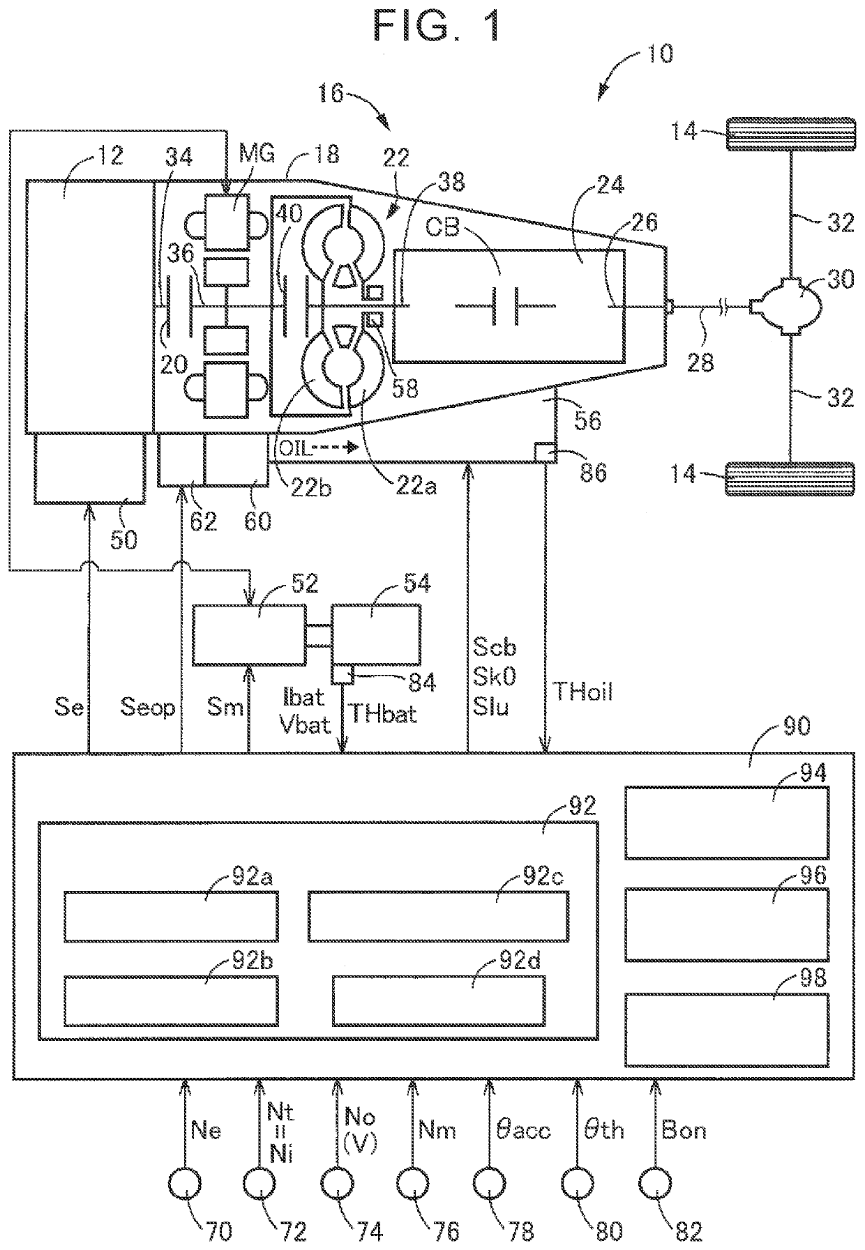
[0031]FIG. 1 illustrates a schematic configuration of a vehicle 10 to which the present disclosure is applied, illustrating an essential portion of the control function and the control system for various types of control for the vehicle 10. In FIG. 1, the vehicle 10 is a hybrid vehicle including an engine 12 and a motor MG which are drive force sources for travel. The vehicle 10 also includes drive wheels 14 and a power transmission device 16 provided in a power transmission path between the engine 12 and the drive wheels 14.

[0032]The engine 12 is a known internal combustion engine such as a gasoline engine and a diesel engine. Engine torque Te, which is output torque of the engine 12, is controlled by an electronic control unit 90, to be discussed later, controlling an engine control device 50, which includes a throttle actuator, a fuel injection device, an ignition device...


PUM


Abstract

An electronic control unit is configured to: output a first command value to the hydraulic control circuit system and then output a second command value to the hydraulic control circuit system during a transition in which the control state of the clutch is switched from a disengaged state to an engaged state when starting the engine; perform first control in which the motor outputs the cranking torque, and second control in which the engine starts operation, when starting the engine; and when the vehicle is in a predetermined state in which a required hydraulic pressure is not secured stably when starting the engine, start output of the first command value when the vehicle is not in the predetermined state, the required hydraulic pressure being a hydraulic pressure supplied from the hydraulic control circuit system to the clutch actuator and required to switch the control state of the clutch.

Description

CROSS-REFERENCE TO RELATED APPLICATION[0001]This application claims priority to Japanese Patent Application No. 2020-171554 filed on Oct. 9, 2020, incorporated herein by reference in its entirety.BACKGROUND1. Technical Field[0002]The present disclosure relates to a control device for a vehicle including an engine, a motor, and a clutch that can couple and decouple the engine and the motor to and from each other.2. Description of Related Art[0003]There is well known a control device for a vehicle including an engine, a motor coupled to a power transmission path between the engine and drive wheels so as to be able to transmit power, and a clutch which is provided between the engine and the motor in the power transmission path and the control state of which is switchable by controlling a hydraulic clutch actuator. Japanese Unexamined Patent Application Publication No. 2015-51728 (JP 2015-51728 A) describes an example of such a control device for a hybrid vehicle. JP 2015-51728 A disclo...

Claims


Application Information

Patent Timeline
Patent Type & Authority Applications(United States)
IPC IPC(8): B60K6/387B60K6/48B60W10/02B60W20/40
CPCB60K6/387B60K6/48B60W10/06B60W20/40B60W10/0235B60W10/023B60W20/00B60K2006/4825B60K2006/268B60K6/26B60W2710/022B60W10/02B60W10/08B60W2710/083Y02T10/62B60W2510/06B60W2510/0225B60W2710/021
Inventor MATSUBARA, KEIGOBABA, MASAYUKIINAYOSHI, TOMOYA
Owner TOYOTA JIDOSHA KK
Why Eureka
Try Eureka