
Laminated Electronic Device and Manufacturing Method Thereof

a technology of laminated electronic devices and manufacturing methods, applied in the direction of fixed capacitor details, inductances, fixed capacitor terminals, etc., can solve the problems of reducing the size of components and limited space that can be used, so as to improve the q value of the product, improve the utilization of space, and reduce the effect of stray capacitan

Pending Publication Date: 2022-04-14
SHENZHEN SUNLORD ELECTRONICS
View PDF0 Cites 0 Cited by
  • Summary
  • Abstract
  • Description
  • Claims
  • Application Information

AI Technical Summary

Benefits of technology

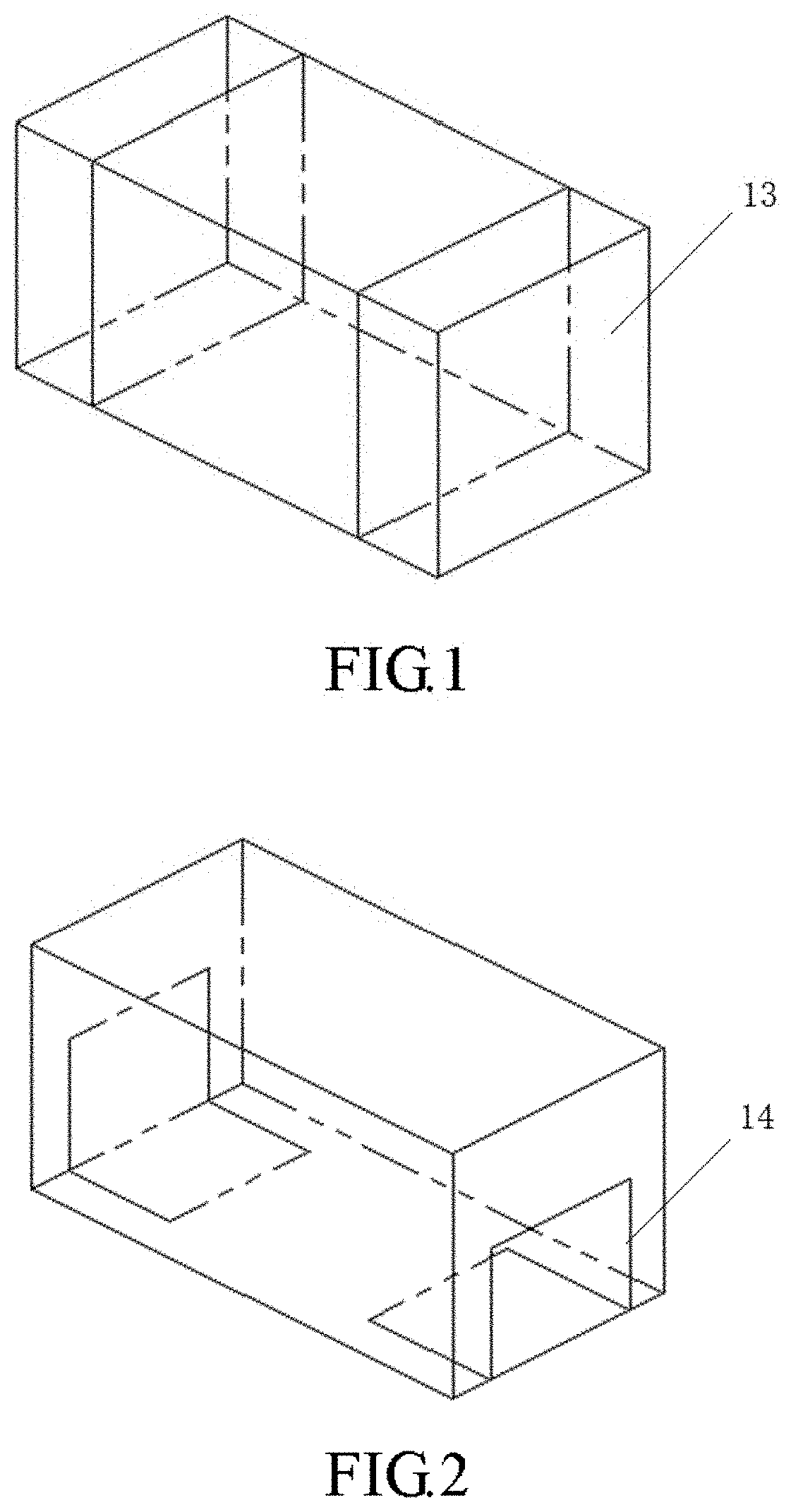
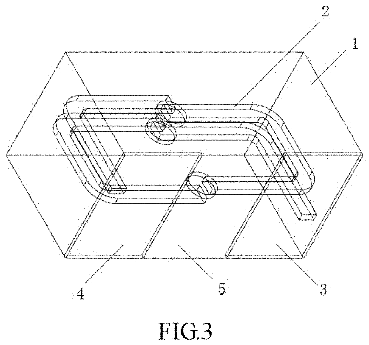
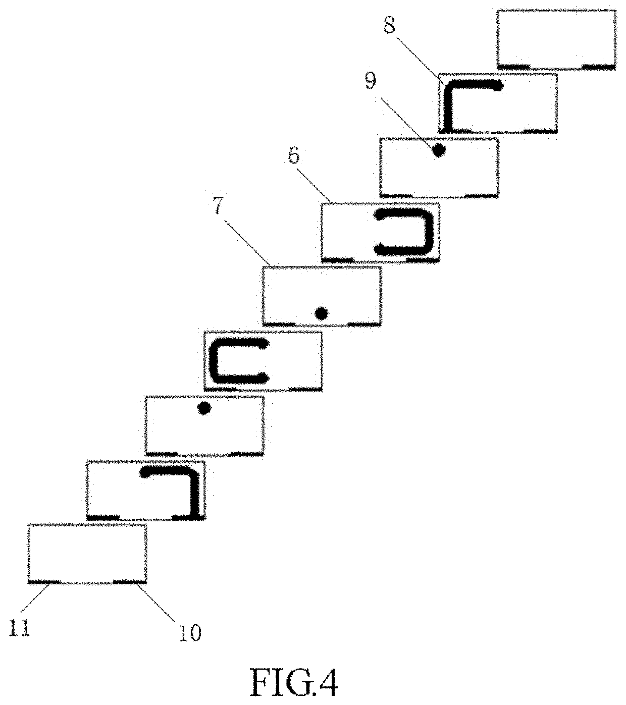
The present application provides a laminated electronic device with a plurality of insulator layers and an internal coil formed by a multi-layer coil pattern. The device includes bottom electrodes that serve as both the connection points for the internal coil and the soldering board, allowing for seamless placement of components and saving space. The internal coil is perpendicular to the bottom electrodes, reducing stray capacitance and improving the product's quality. This design also allows for higher-density mounting and better space utilization.

Problems solved by technology

Therefore, from the components themselves, it is relatively difficult to reduce the size of the components in a short time, and the space that can be reduced is also very limited.

Method used


Image

  • Laminated Electronic Device and Manufacturing Method Thereof
  • Laminated Electronic Device and Manufacturing Method Thereof
  • Laminated Electronic Device and Manufacturing Method Thereof

Examples


Embodiment Construction

[0029]The embodiments of the present invention will be described in detail below. It should be noted that the following description is exemplary only and is not intended to limit the scope of the present application and its use.

[0030]It should be noted that when an element is referred to as being “fixed to” or “disposed on” another element, it can be directly on the other element or indirectly on the other element. When an element is referred to as being “connected to” another element, it can be directly connected to the other element or indirectly connected to the other element. In addition, the connection may be for either fixation or coupling or communication.

[0031]It is to be understood that the terms “length, width, upper, lower, front, rear, left, right, vertical, horizontal, top, bottom, inner, outer”, and the like, refer to orientations or positional relationships based on the orientations or positional relationships shown in the figures. It is merely for the purpose of desc...


PUM

PropertyMeasurementUnit
sizeaaaaaaaaaa
densityaaaaaaaaaa
structureaaaaaaaaaa

Abstract

A laminated electronic device includes a laminate wherein the laminate includes a plurality of laminated insulator layers, the laminate has a multi-layer coil pattern provided between the plurality of insulator layers in a laminated manner, adjacent layers of the coil pattern are electrically connected through conductive via holes to form an internal coil, a first external electrode and a second external electrode are disposed on a bottom surface of the laminate which is parallel to a direction of lamination. In surface-mounting of the laminated electronic device, it only needs to connect the external electrodes on the bottom surface of the laminate to a soldering board, and needs not to preserve a space for solder wicking in the surrounding, thereby significantly saving the occupied space of surface mount components to achieve high-density mounting; in addition, the Q value of the product is improved.

Description

CROSS REFERENCE TO RELATED APPLICATIONS[0001]This application is a continuation application of PCT / CN2020 / 120386 filed on 2020 Oct. 12. The contents of the above-mentioned application are all hereby incorporated by reference.BACKGROUND OF THE INVENTION1. Field of the Invention[0002]The present application relates to electronic devices, and more particularly, to a laminated electronic device and a manufacturing method thereof.2. Description of the Prior Art[0003]In recent years, with the increasing popularity of wearable devices, new devices, such as smart bracelets, Bluetooth earphones, etc., have begun to be accepted by people, and due to the small size and rich functions of such devices, they require miniaturization and high density of electronic components and electronic circuits.[0004]As the smart phone has more and more functions and people requires for better battery life, space for the components is gradually reduced. In order to meet the needs of customers, a large number of...

Claims


Application Information

Patent Timeline
Patent Type & Authority Applications(United States)
IPC IPC(8): H01F27/28H01F27/29H01F41/04H01F41/10
CPCH01F27/2804H01F27/292H01F2027/2809H01F41/10H01F41/041H01F17/0013H01G4/232
Inventor LU, DAFUQIN, JIEYONGLIANG, ZHENRENLI, SHUYAN
Owner SHENZHEN SUNLORD ELECTRONICS
Learn More