
Grain-oriented electrical steel sheet

a technology of electrical steel sheet and grain orientation, which is applied in the direction of heat treatment apparatus, magnetic bodies, furnaces, etc., can solve the problems of adversely affecting iron losses, and affecting the movement of magnetic domain walls, and achieve excellent coating adhesion and excellent iron loss

Pending Publication Date: 2022-04-21
NIPPON STEEL CORP
View PDF5 Cites 0 Cited by
  • Summary
  • Abstract
  • Description
  • Claims
  • Application Information

AI Technical Summary

Benefits of technology

The present invention provides a tension-insulation coating-attached grain-oriented electrical steel sheet that has excellent iron loss and coating adhesion. This means that this sheet has the ability to convert magnetic energy into electrical energy with low loss and the coating is securely attached to the sheet.

Problems solved by technology

However, it has been clarified that forsterite films hinder the movement of magnetic domain walls and adversely affect iron losses.
The smooth and rapid movement of these magnetic domain walls is effective for the reduction of iron losses, but forsterite films have an uneven structure in the steel sheet / film interfaces, and the uneven structure hinders the movement of magnetic domain walls, and thus forsterite films adversely affect iron losses.

Method used


Image

  • Grain-oriented electrical steel sheet
  • Grain-oriented electrical steel sheet

Examples


example 1

[0137]Silicon steel slabs having a component composition (the remainder was Fe and an impurity) shown in Table 1 were heated to 1100° C. and hot-rolled to produce hot-rolled steel sheets having a sheet thickness of 2.6 mm, the hot-rolled steel sheets were annealed at 1100° C. and then cold-rolled once to produce cold-rolled steel sheets having a final sheet thickness of 0.23 mm, and decarburization annealing and nitriding annealing were performed on the cold-rolled steel sheets.

TABLE 1Chemical component (mass %)Slab No.CSiMnAlSa0.0073.000.010.0150.0050b0.0023.801.400.0250.0010c0.0756.500.200.0500.0008d0.0023.801.400.0250.0010

[0138]Next, an aqueous slurry of an annealing separating agent mainly containing alumina was applied to the cold-rolled steel sheets that had undergone decarburization annealing and nitriding annealing, and final annealing was performed at 1200° C. for 20 hours, thereby obtaining grain-oriented electrical steel sheets in which no forsterite film was present on t...

example 2

[0147]Silicon steel slabs having a component composition shown in Table 1 were heated to 1100° C. and hot-rolled to produce hot-rolled steel sheets having a sheet thickness of 2.6 mm, the hot-rolled steel sheets were annealed at 1100° C. and then cold-rolled once to produce cold-rolled steel sheets having a final sheet thickness of 0.23 mm, and decarburization annealing and nitriding annealing were performed on the cold-rolled steel sheets.

[0148]Next, an aqueous slurry of an annealing separating agent mainly containing alumina was applied to the cold-rolled steel sheets that had undergone decarburization annealing and nitriding annealing, and final annealing was performed at 1200° C. for 20 hours, thereby obtaining grain-oriented electrical steel sheets in which there was no forsterite film on the steel sheet surface having a mirror gloss and secondary recrystallization was completed.

[0149]A soaking treatment was performed on the grain-oriented electrical steel sheets in an atmosphe...


PUM

PropertyMeasurementUnit
temperatureaaaaaaaaaa

Abstract

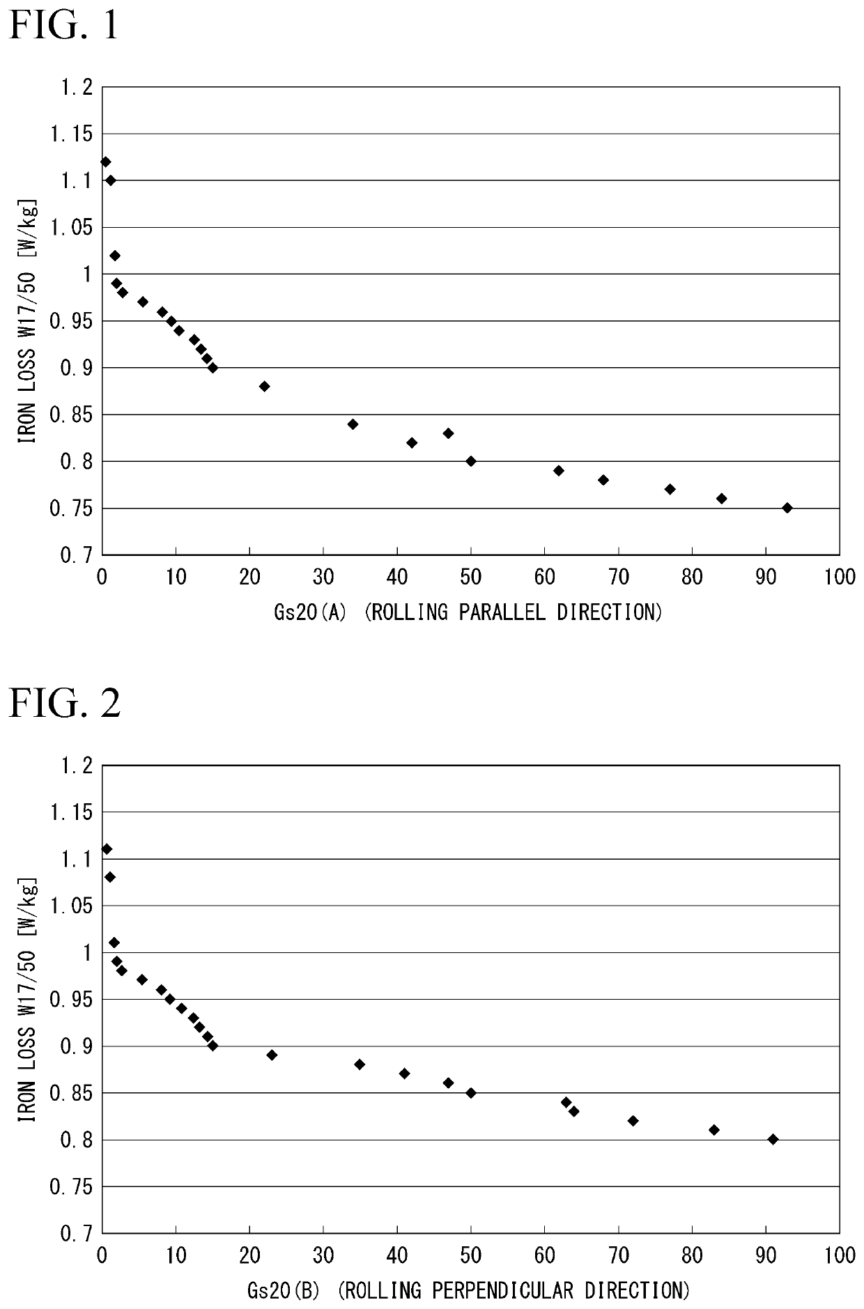
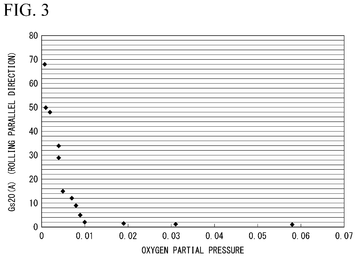
A grain-oriented electrical steel sheet of the present invention has a base steel sheet, an amorphous oxide layer formed on the base steel sheet, and a tension-insulation coating formed on the amorphous oxide layer, in which the base steel sheet contains, as a chemical composition, by mass %, C: 0.085% or less, Si: 0.80 to 7.00%, Mn: 1.50% or less, acid-soluble Al: 0.065% or less, S: 0.013% or less, Cu: 0 to 0.80%, N: 0 to 0.012%, P: 0 to 0.50%, Ni: 0 to 1.00%, Sn: 0 to 0.30%, and Sb: 0 to 0.30%, a remainder is Fe and an impurity, a surface glossiness Gs20(A) in a direction parallel to a rolling direction is 2.0 to 70, and a surface glossiness Gs20(B) in a direction perpendicular to the rolling direction is 2.0 to 70.

Description

TECHNICAL FIELD[0001]The present invention relates to a grain-oriented electrical steel sheet that is used as an iron core material of transformers and particularly to a tension-insulation coating-attached grain-oriented electrical steel sheet having excellent adhesion of the tension-insulation coating.[0002]Priority is claimed on Japanese Patent Application No. 2019-005475, filed Jan. 16, 2019, the content of which is incorporated herein by reference.BACKGROUND ART[0003]Grain-oriented electrical steel sheets are mainly used in transformers. Transformers are continuously excited for a long period of time from installation to disposal and continuously cause energy losses, and thus energy losses caused when transformers are magnetized by alternating currents, that is, iron losses, serve as a critical index for determining the performance of transformers.[0004]In order to reduce the iron losses of grain-oriented electrical steel sheets, a number of techniques have been thus far develop...

Claims


Application Information

Patent Timeline
Patent Type & Authority Applications(United States)
IPC IPC(8): C21D9/46C21D8/12C21D8/02C22C38/00C22C38/02C22C38/04C22C38/06C22C38/08C22C38/16C22C38/60
CPCC21D9/46C21D2201/05C21D8/1222C21D8/1233C21D8/0257C21D8/1272C22C38/001C22C38/002C22C38/008C22C38/02C22C38/04C22C38/06C22C38/08C22C38/16C22C38/60C21D8/1283C21D6/008C21D8/1255C21D1/76H01F1/14791H01F1/18C23C22/74C23C22/08C22C38/004Y02P10/20C23C22/00H01F1/147C22C38/12H01F1/14783
Inventor TAKATANI, SHINSUKEARITA, YOSHIHIROOKUMURA, SHUNSUKENAGANO, SHOHJI
Owner NIPPON STEEL CORP
Learn More