
Biometric authentication device and biometric authentication method

Pending Publication Date: 2022-04-21
HITACHI LTD
View PDF0 Cites 1 Cited by
  • Summary
  • Abstract
  • Description
  • Claims
  • Application Information

AI Technical Summary

Benefits of technology

The invention provides a device and method for biometric authentication that can accurately verify a person's identity even when the lighting environment is variable during imaging. It can also handle reflections from unexpected subjects and achieve accurate verification.

Problems solved by technology

In particular, when unwanted ambient light such as sunlight shines into the environment around the device, strong light is reflected from the ceiling and walls of the room, and unwanted objects are reflected in the background of the finger, making it impossible to implement the detection process of the shooting position and posture of the finger correctly, which results in degradation of authentication accuracy.
However, the background separation disclosed in JP-A-2020-123068 (PTL 2) only works correctly when the ambient light is of a specific wavelength and intensity, and there is no mention of a background separation technique that can be implemented in a variety of environments.
The above-mentioned problems are not limited to fingers, but also apply to various other living organisms such as the user's palm, back of the hand, and face.
Thus, the conventional technology cannot correctly detect the position and posture of a living body under various ambient light environments in biometric authentication using various living bodies including multiple fingers, which leads to a decrease in authentication accuracy.

Method used


Image

  • Biometric authentication device and biometric authentication method
  • Biometric authentication device and biometric authentication method
  • Biometric authentication device and biometric authentication method

Examples


first embodiment

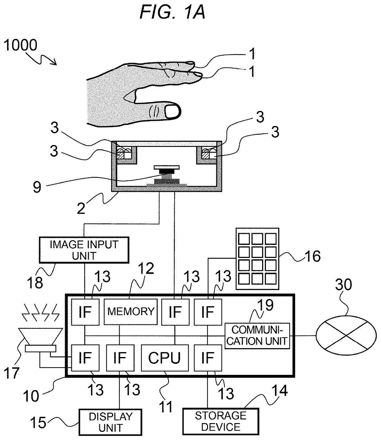
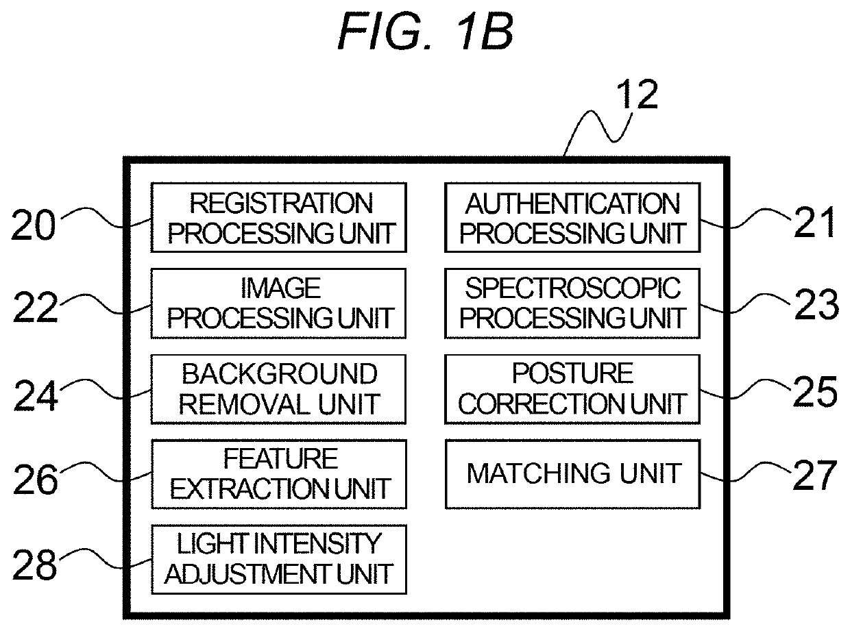
[0037]FIG. 1A shows an example of the overall configuration of a biometric authentication system 1000 that uses the biometric features of the fingers of a hand in the present embodiment. It goes without saying that the configuration of the present embodiment is not a system, but may be configured as a device with all or part of the configuration mounted on a chassis. The device may be a personal authentication device that includes authentication processing, or it may be a finger image acquisition device or finger feature image extraction device that specializes in acquiring finger images while authentication processing is performed outside the device. It may also be implemented as a terminal. A configuration with at least an imaging unit that captures images of a living body and an authentication processing unit that processes the captured images and authenticates the living body is called a biometric authentication device.

[0038]The biometric authentication system 1000 shown in FIG....

second embodiment

[0091]A second embodiment is an embodiment of a technology that uses the image capturing device shown in the first embodiment and images of a subject consisting of multiple wavelengths to estimate the range between the camera and the subject pixel by pixel, and uses this information to correct and guide the deformation of the subject, thereby increasing the accuracy of biometric authentication.

[0092]FIGS. 9A and 9B show the principle of range measurement of a subject using visible light and infrared light images. In the present embodiment, a living body is photographed by light sources of different wavelengths. In general, the optical characteristics of the camera lens, such as the refractive index, differ slightly for each wavelength, so the image formation position and focus may differ for each wavelength. Therefore, when images are checked at different wavelengths, the image at one wavelength may be in focus, but the image at the other wavelength may be out of focus and blurred, ...

third embodiment

[0102]A third embodiment describes an example of an authentication device based on the technology illustrated in the first and the second embodiment, which is non-contact, intuitively guides the user to the position where the biometric is presented, and is robust to changes in environmental lighting.

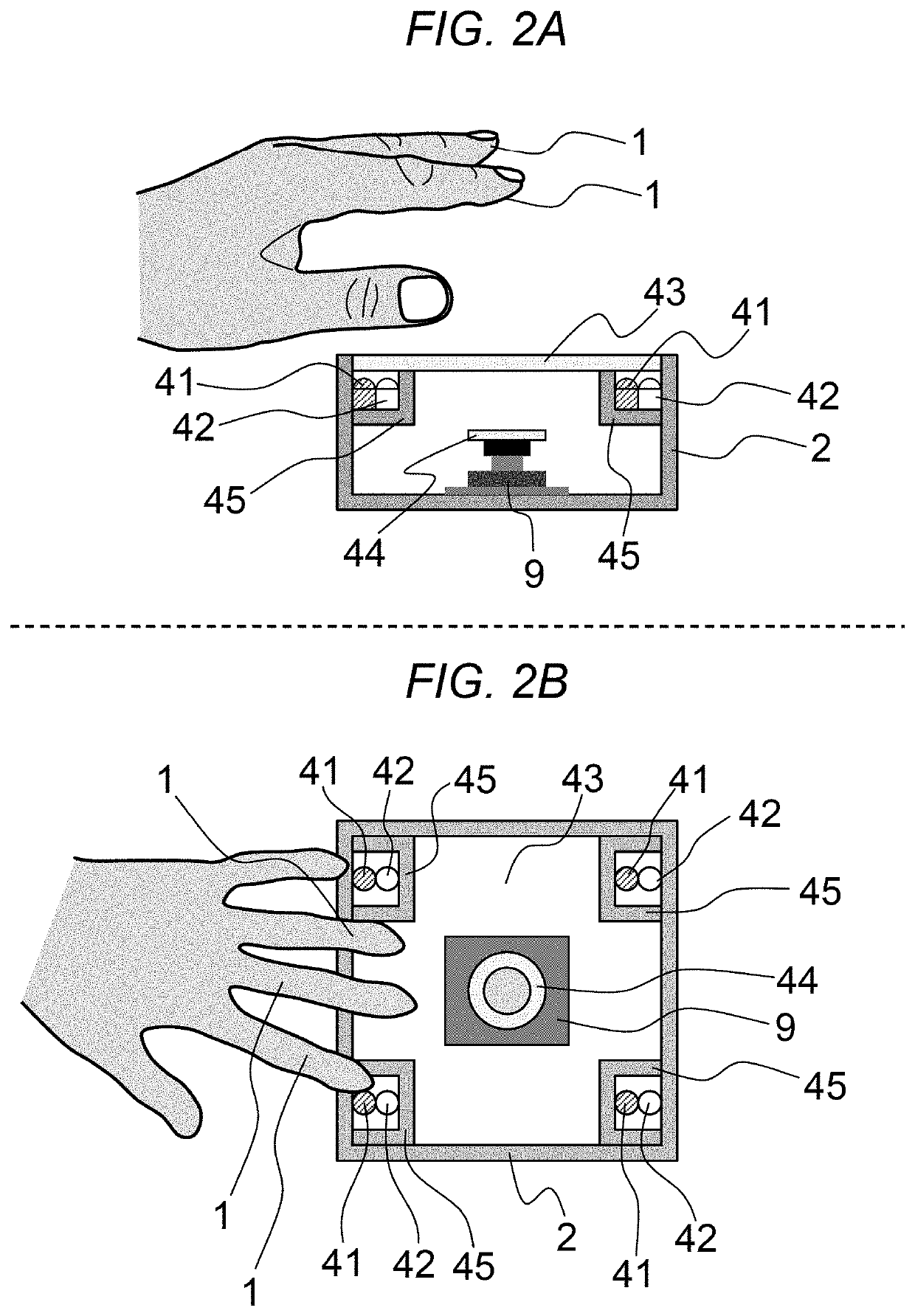
[0103]FIGS. 11A and 11B show an embodiment of a biometric authentication device that performs contactless authentication by guiding the position of a fingertip. A camera 9 is equipped inside the input device 2, and visible light sources 41 and infrared light sources 42 are arranged in a circle around it. The visible light sources 41 and the infrared light sources 42 can irradiate light uniformly to the finger 1 held above, and the intensity of each light source can be controlled independently as shown in the first embodiment. Although only one finger is shown in FIGS. 11A and 11B, as in the first embodiment above, multiple fingers can be used, for example, just one index finger.

[0104]Two...


PUM


Abstract

The objective is to achieve highly accurate authentication even when there is variation in the ambient light environment during biometric imaging. A biometric authentication device includes an image capturing unit that captures images of a living body, a light source for capturing images of the living body, an optical filter that selectively passes and blocks light according to wavelength, a spectroscopic processing unit that separates multiple wavelengths captured simultaneously, respectively, and a calculation unit that calculates the shape and posture of a predetermined part of the living body in the captured images, a background removal unit that removes the background from the image of the living body using the spectral images of the living body and the spectral image of the unwanted ambient light, and an authentication unit that performs biometric authentication using the image of the predetermined part.

Description

BACKGROUND OF THE INVENTION1. Field of the Invention[0001]The present invention relates to a biometric authentication device and a biometric authentication method that authenticate an individual using biometric information.2. Description of Related Art[0002]Among the various biometric authentication technologies, finger vein authentication is known for its high authentication accuracy. Finger vein authentication uses the complex blood vessel patterns inside the finger to achieve high authentication accuracy, and is more difficult to forge or tamper with than fingerprint authentication, thus providing a high level of security.[0003]In recent years, cashless payment methods, such as Quick Response (QR) code payments linked to personal smartphones, are becoming popular in retail stores such as convenience stores and restaurants. These payment methods are highly convenient because they do not require cash payment, and they can also be linked to various point services to increase custome...

Claims


Application Information

Patent Timeline
IPC IPC(8): G06K9/00G06K9/62G06K9/20G06T7/194G06K9/46
CPCG06K9/00912G06K9/6215G06K9/2018G06T7/194G02B5/20G06K9/2036G06T2207/20084G06T2207/20081G06T2207/10048G06K9/4661G06N3/04G06N3/08G06V40/1318G06V40/50G06V10/143G06V40/67G06V10/454G06V10/58G06V10/774G06V10/82G06V40/14G06T7/11G06T7/136G06T2207/10024G06T7/174G06T7/55G06V40/1324G06V40/1365G06V10/60G06V10/145G06F18/22
Inventor MIURA, NAOTOMATSUDA, YUSUKENAGASAKA, AKIONONOMURA, YONAKAZAKI, KEIICHIRO
Owner HITACHI LTD
Learn More