Device and method for producing three-dimensional workpieces

Pending Publication Date: 2022-05-05
SLM SOLUTIONS GRP
View PDF5 Cites 0 Cited by
  • Summary
  • Abstract
  • Description
  • Claims
  • Application Information

AI Technical Summary

Benefits of technology

[0034]It can thus be ensured that the gas inlet is always at a constant height above the uppermost raw material powder layer. The gas inlet can thereby be mechanically rigidly coupled with the irradiation unit. If a gas outlet is additionally provided, the vertical movement device can further be adapted to move the irradiation unit vertically together with the gas inlet and the

Problems solved by technology

Depending on the size of the installation and the size of a corresponding build space, the lifting mechanism used may thereby reach its load limits, which would require a more complex and thus more expensive lifting mechanism.
Furthermore, the weight to be moved by the lifting mechanism changes during the build process.
This c

Method used


Image

  • Device and method for producing three-dimensional workpieces
  • Device and method for producing three-dimensional workpieces
  • Device and method for producing three-dimensional workpieces

Examples


Embodiment Construction

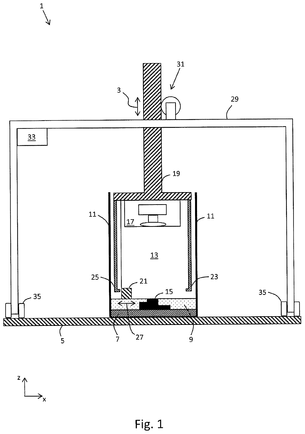
[0052]In FIG. 1, a first exemplary embodiment of a device 1 according to the invention is shown in a schematic side view. The views of the figures are not necessarily true to scale. A vertical direction (also z-direction hereinbelow) is defined in the figure by the arrow 3, and a horizontal plane (also x-y plane hereinbelow) extends perpendicular to the plane of the drawing along the base 5.

[0053]The base 5 represents a baseplate of the device 1. The device 1 can further have an outer housing (not shown) with outside walls and an outside cover. The device 1 can, however, also be provided without its own outer housing in an open construction, for example in a factory building.

[0054]On the base 5 there is provided a carrier 7 which has a horizontal rectangular surface. The carrier 7 is connected in a stationary manner to the base 5 and is adapted to receive a plurality of layers of raw material powder 9. Adjacent to the carrier 7 at the sides is a build chamber wall 11, which surround...


PUM

PropertyMeasurementUnit
Thicknessaaaaaaaaaa

Abstract

The invention relates to a device (1) for producing three-dimensional workpieces (15), comprising a carrier (7) for receiving raw material powder (9), a build chamber wall (11, 11a, 11b) which extend substantially vertically and which is adapted to laterally delimit and support the raw material powder (9) applied to the carrier (7); an irradiation unit (17) for selectively irradiating the raw material powder (9) applied to the carrier (7) with electromagnetic radiation or particle radiation in order to produce on the carrier (7) a workpiece (15) manufactured from the raw material powder (9) by an additive layer building method, wherein the irradiation unit (17) comprises at least one optical element; and a vertical movement device (31) which is adapted to move the irradiation unit (17) vertically relative to the carrier (7). The build chamber wall (11, 11a, 11b) and the carrier (7) are adapted to be connected to one another in a stationary manner during the vertical movement of the irradiation unit (17) so that the vertical movement takes place relative to the carrier (7) and relative to the build chamber wall (11, 11a, 11b).

Description

CROSS-REFERENCE TO RELATED APPLICATIONS[0001]This application is a continuation of pending U.S. application Ser. No. 16 / 495,958 filed on Sep. 20, 2019, which is the U.S. national phase of international application PCT / EP2018 / 055770, filed on Mar. 8, 2018, which claims the benefit of German application DE 10 2017 205 027.6 filed on Mar. 24, 2017; all of which are hereby incorporated herein in their entirety by reference.BACKGROUND AND SUMMARY[0002]The invention relates to a device and a method for producing three-dimensional workpieces. In particular, the invention relates to a device and a method for producing three-dimensional workpieces by means of an additive layer building method.[0003]In additive methods for the manufacture of three-dimensional workpieces, and in particular in additive layer building methods, it is known to apply an initially shapeless or shape-neutral molding compound (for example a raw material powder) to a carrier layer by layer and to solidify it by locatio...

Claims


Application Information

Patent Timeline
IPC IPC(8): B29C64/153B33Y10/00B33Y30/00B33Y40/00B33Y50/02B29C64/232B29C64/393B29C64/371B28B1/00B28B17/00B22F10/20
CPCB29C64/153B33Y10/00B33Y30/00B33Y40/00B33Y50/02B22F10/30B29C64/393B29C64/371B28B1/001B28B17/0081B22F10/20B29C64/232B22F12/00B22F12/50B22F12/30B22F12/41B22F10/28B29C64/20B29C64/277B29C64/245B29C64/321B29C64/259Y02P10/25B22F12/222B22F12/224B22F12/38B22F2999/00B22F12/70B22F12/86B22F12/49B22F10/32B22F12/44B22F10/322B22F12/53B22F12/63B22F2203/00
Inventor KROL, TONI ADAMROLINK, GESAHAACK, BODOHOPPE, BIRK
Owner SLM SOLUTIONS GRP
Why Eureka
Try Eureka