
Flexible display device

a display device and flexible technology, applied in the field of displays, can solve the problems of unnecessary deformation, peeling of thin-film layers, and shearing of devices edges, and achieve the effects of reducing the risk of squeezing, increasing the ability to resist an external impact on the screen body, and effective improving the accuracy of assembling the devi

Active Publication Date: 2022-05-05
WUHAN CHINA STAR OPTOELECTRONICS SEMICON DISPLAY TECH CO LTD
View PDF0 Cites 0 Cited by
  • Summary
  • Abstract
  • Description
  • Claims
  • Application Information

AI Technical Summary

Benefits of technology

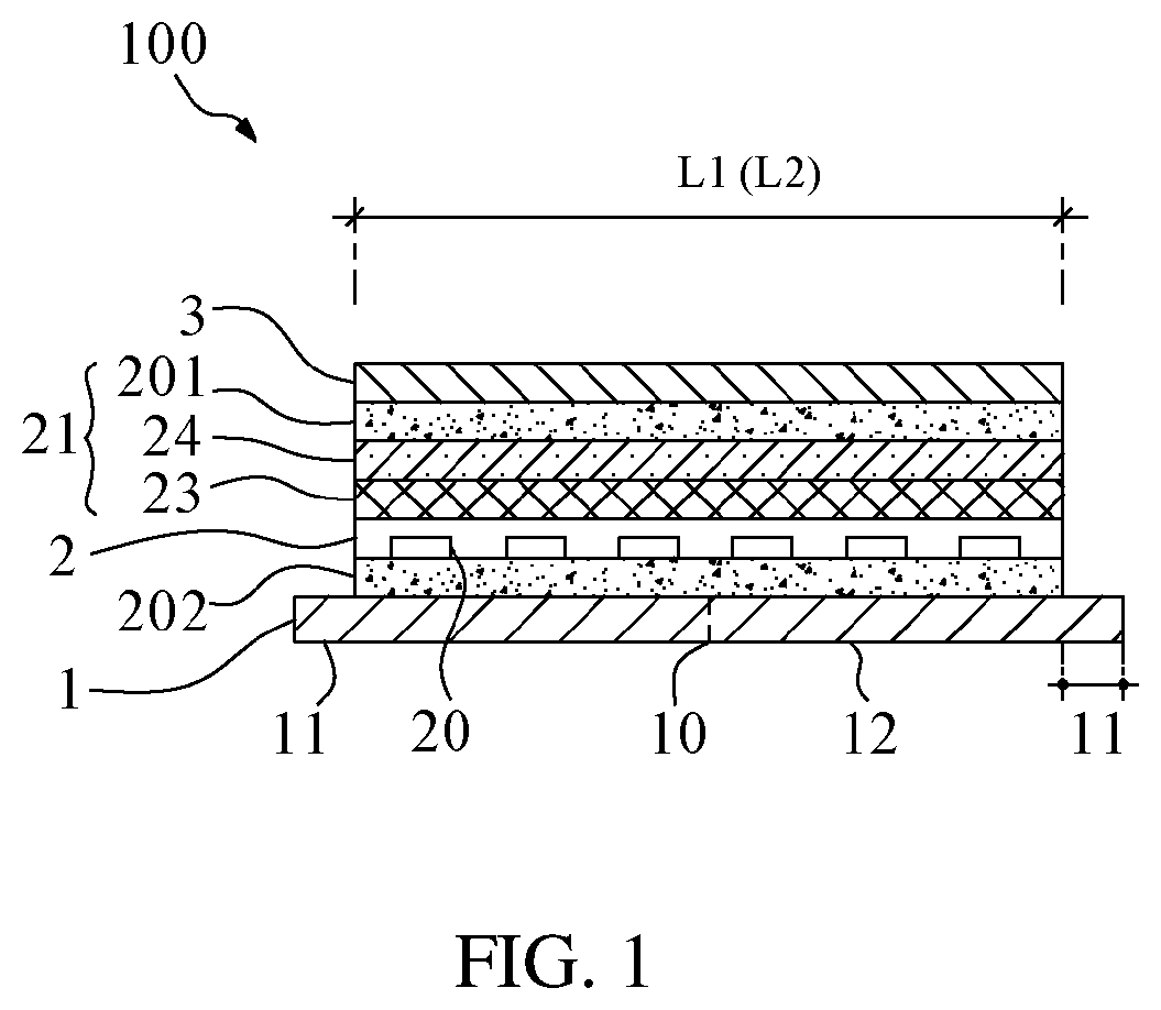
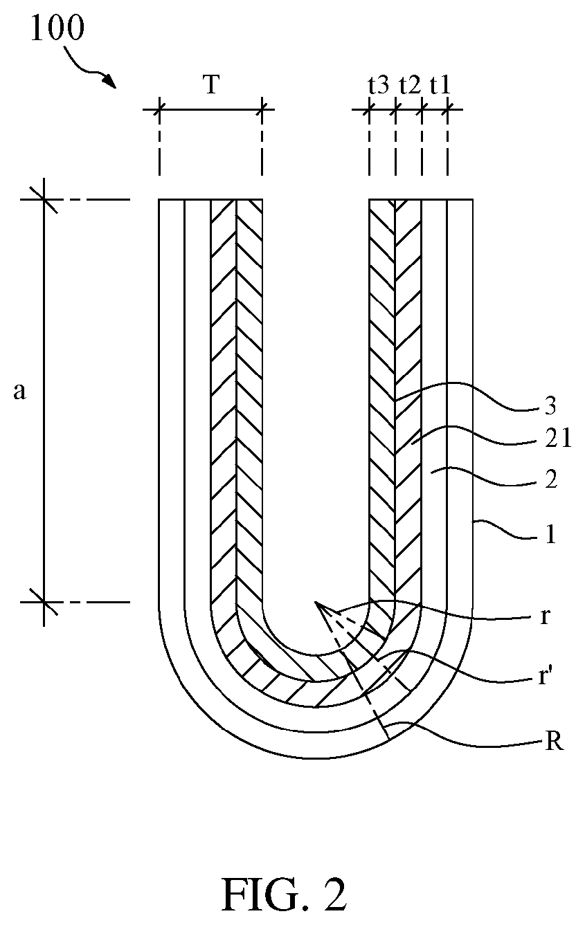
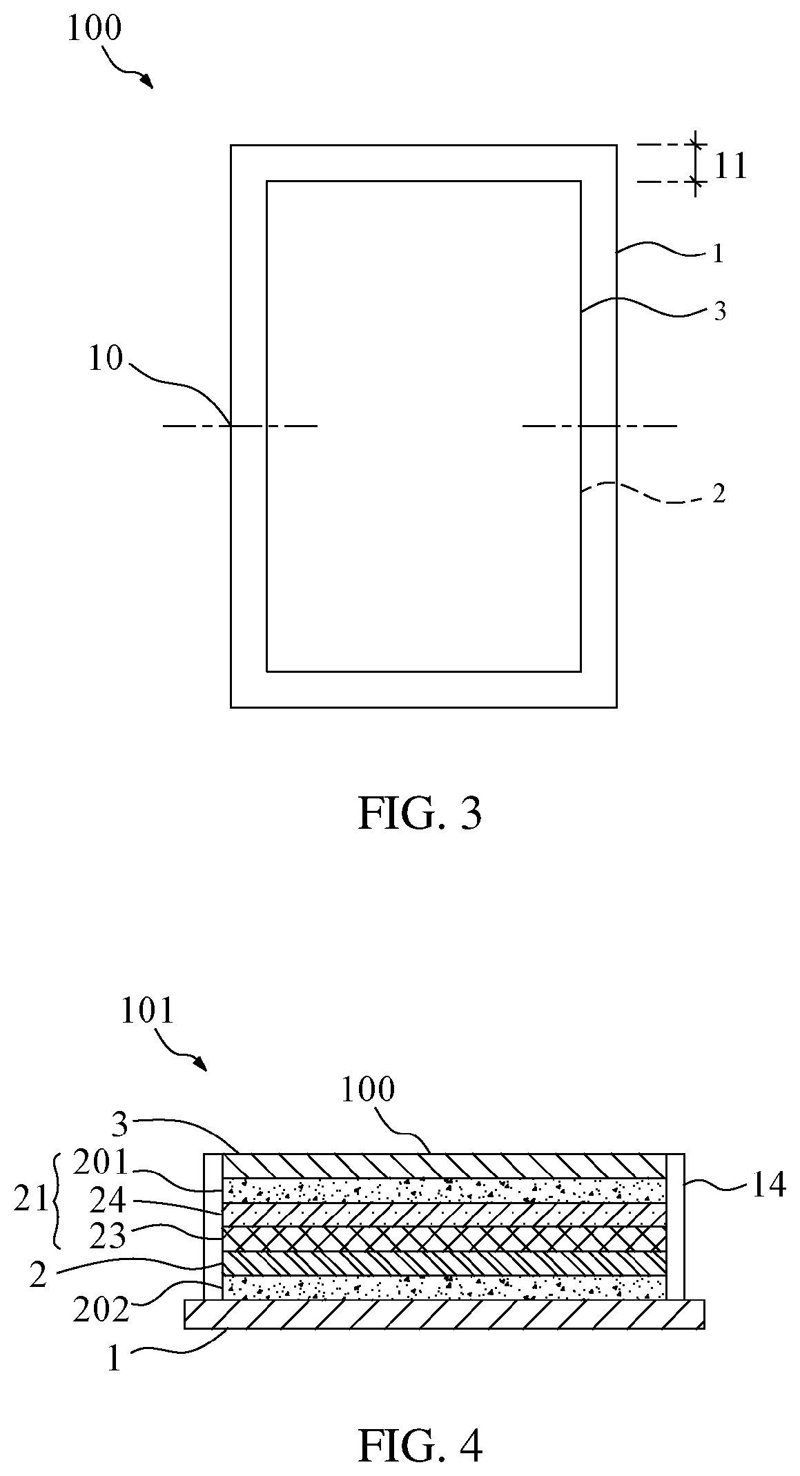
The present invention provides a flexible display device that has outer edges that are flush with inner film layer structures in a bent state. This improves assembly accuracy, reduces the risk of peeling of components, and ensures a product lifespan. The flexible display device has a support area and extension areas on opposite sides of the bending axis. The edges of the flexible display panel, functional film layer, and flexible cover are flush with the extension areas when bended. This minimizes sheared edges, increases resistance to external impacts, and prevents light leakage, thereby improving assembly accuracy and display performance and lifespan of the flexible display device.

Problems solved by technology

In a situation that stack structures bend inward, edges of devices will inevitably be sheared due to differences between inner and outer radiuses.
That is, after bending, edges of the thin-film layers are not flush with each other, thereby easily resulting in peeling of the thin-film layers.
As a result, materials such as flexible covers on insides of display devices will be subject to compressive stress from structural casings (i.e. supporting materials) on outer sides, causing unnecessary deformation and increasing the risk of peeling of components.

Method used


Image

  • Flexible display device
  • Flexible display device
  • Flexible display device

Examples


Embodiment Construction

[0021]The following embodiments are referring to the accompanying drawings for exemplifying specific implementable embodiments of the present invention. Directional terms described by the present invention, such as upper, lower, front, back, left, right, inner, outer, side, etc., are only directions by referring to the accompanying drawings, and thus the used directional terms are used to describe and understand the present invention, but the present invention is not limited thereto.

[0022]The present application relates to a flexible display device, and particularly to a flexible display device capable of being self-luminous using organic light-emitting materials and being bendable to deform in a bent state or an expended state. The flexible display device of the present application can provide users with various usage patterns, including transformation of small-sized mobile phones or large-sized tablets by bending, and product reliability of the display device will not be affected ...


PUM

PropertyMeasurementUnit
lengthaaaaaaaaaa
thicknessaaaaaaaaaa
flexibleaaaaaaaaaa

Abstract

A flexible display device includes a flexible display panel bendable along a bending axis. A support backplate is disposed on a side of the flexible display panel and located on an outer side of the flexible display panel when bending. The support backplate includes a support area and a plurality of extension areas defined on opposite sides of the bending axis and adjoining two sides of the support area. When the flexible display device is in an expanded state, a difference value between a length of the support backplate and a length of the flexible display panel in a direction perpendicular to the bending axis is greater than or equal to a first threshold. The flexible display device can reduce the risk of peeling of components in a bent state and can ensure a product lifespan.

Description

BACKGROUND OF INVENTION1. Field of Invention[0001]The present invention relates to a technical field of displays, and particularly to, a flexible display device.2. Related Art[0002]Currently, foldable flexible organic light-emitting diode (OLED) display devices have been put on the market, facilitating simple and convenient lives.[0003]Foldable flexible OLED display devices are receiving widespread attention. Reliability and durability of display devices are key factors to determine whether the devices can quickly grab the market. General foldable flexible display devices include flexible covers, adhesives, functional layers, flexible display devices, adhesives, and supporting materials from top to bottom. The supporting materials are rigid materials. Each of thin-film layers has a certain thickness. In a situation that stack structures bend inward, edges of devices will inevitably be sheared due to differences between inner and outer radiuses. That is, after bending, edges of the t...

Claims


Application Information

Patent Timeline
Patent Type & Authority Applications(United States)
IPC IPC(8): H01L51/52B32B7/12
CPCH01L51/5237B32B7/12B32B2457/208H01L27/3244B32B2307/41B32B2307/42B32B2307/412G09F9/301H10K59/8731B32B15/18B32B3/085B32B2307/732B32B2457/206H10K2102/311B32B3/02B32B15/04B32B2250/02B32B2250/03B32B2250/04B32B2250/05B32B2307/7376B32B7/023H10K50/84H10K59/12
Inventor ZHANG, ZHUOLEE, HAOCHUNHOU, XIAOMENG
Owner WUHAN CHINA STAR OPTOELECTRONICS SEMICON DISPLAY TECH CO LTD
Learn More