Separator plate for an oil mist separator and oil mist separator

a technology of separator plate and oil mist, which is applied in the direction of separation process, machine/engine, mechanical apparatus, etc., can solve the problems of reducing the overall weight of the engine, and reducing the environmental pollution of the piston engin

Active Publication Date: 2022-05-12
HENGST SE
View PDF7 Cites 0 Cited by
  • Summary
  • Abstract
  • Description
  • Claims
  • Application Information

AI Technical Summary

Benefits of technology

[0005]The idea of the invention is based on the observation that, on the one hand, oil mist separators reduce the environmental pollution of piston engines by oil mist, but at the same time increase the overall weight of the engine, which is reflected in increased material costs and, when the piston engines are used to drive motor vehicles, worsened fuel consumption and a thus CO2 balance.

Problems solved by technology

Apart from that, crankshaft housings are usually not designed to withstand these higher pressures.
However, these exhaust gases contain a significant amount of oil mist, which must not be released into the environment.
Furthermore, the symmetrical arrangement counteracts the formation of weld lines that occur when flow fronts in the injection-molding process meet.
As compared to other plastics, however, these plastics have rather poor flow properties, as the melt viscosity is high due to their complex chemical structure.
This often leads to weld lines that worsen mechanical stability and require an increase of wall thicknesses.
So far, for the sake of simplicity, it has been assumed that all spokes are of the same length, but this is not necessarily the case.
However, the webs can be problematic with regard to the formation of weld lines, because the plastic melt in the webs advances the rest of the flow front.
The lowest possible thickness is only limited by the material strength of the separator plate and the viscosity of the oil to be separated.
However, this lower limit depends on the viscosity of the oil to be separated.

Method used


Image

  • Separator plate for an oil mist separator and oil mist separator
  • Separator plate for an oil mist separator and oil mist separator
  • Separator plate for an oil mist separator and oil mist separator

Examples


Embodiment Construction

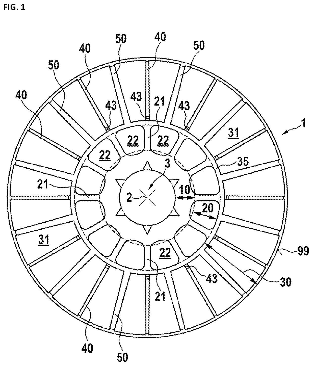
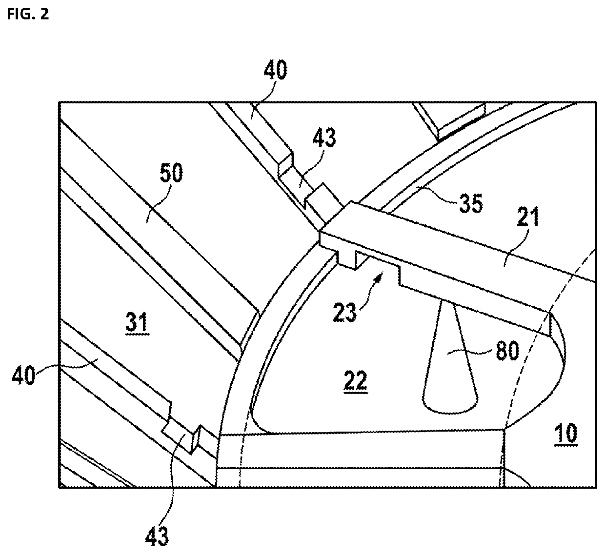
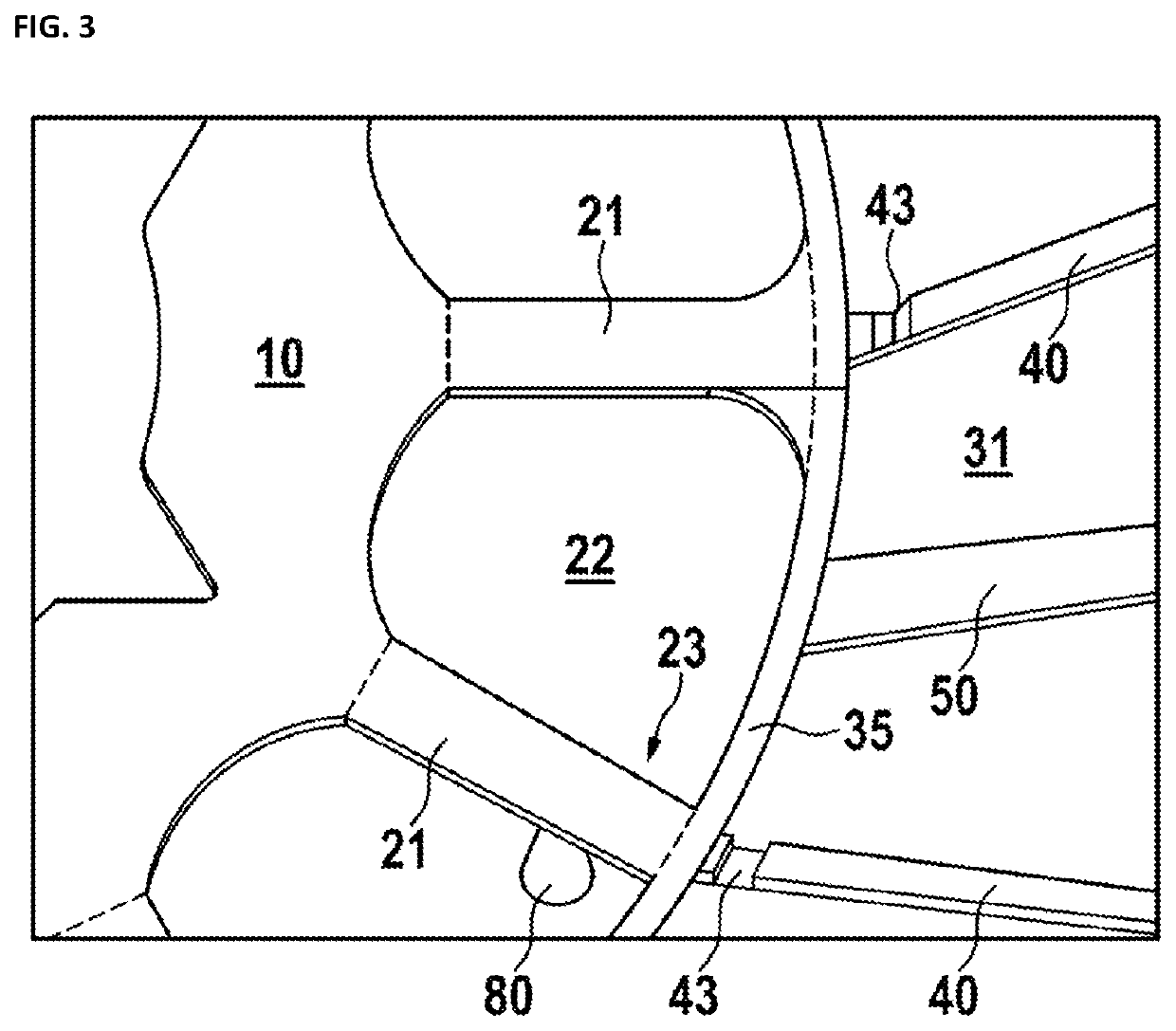
[0043]FIG. 1 shows a plan view of an embodiment of a separator plate 1. As shown, the separator plate 1 has three ring-shaped areas. The first ring area 10 is limited radially on an inward side by a receptacle 3, dimensioned to accept a drive shaft (not shown). The common axis of rotation of the shaft and the separator plate 1 runs orthogonally to the drawing plane and is identified by the reference sign 2. The first ring area 10 merges radially on the outward side with a second ring area 20, which is essentially formed by preferably spatially-evenly arranged spokes 21 and the openings 22 defined by and located between the immediately-neighboring spokes 21. Such openings 22 define the flow channels for the oil mist. The outer ends of the spokes 21 are at a ring 35 that identifies the inner edge of the third ring area 30. The third ring area 30 extends up to the edge 99 of the separator plate 1, which terminates the outer portion of the plate 1 radially. The limits between the ring a...


PUM

PropertyMeasurementUnit
heightaaaaaaaaaa
thicknessaaaaaaaaaa
heightaaaaaaaaaa

Abstract

A separator plate having a receptacle for a drive shaft that defines an axis of rotation. Such plate, which includes a first annular region radially adjacent to the receptacle, a second annular region radially adjacent to the first annular region, and a third annular region radially adjacent to the second annular region, can be produced particularly easily if the second annular region has a plurality of spokes connecting the first and the third annular regions to one another and if there are flow channels extending in the axial direction between the spokes.

Description

BACKGROUND1. Field of the Invention[0001]The invention relates to a separator plate for an oil mist separator, and, in particular for a contraption including a separator plate with a receptacle for a drive shaft that defines an axis of rotation and is configured to separate oil from crankcase gases, as well as an oil mist separator with at least one such separator plate.2. Description of Related Art[0002]During the combustion process in piston engines, a small portion of the exhaust gases flows laterally past the piston or the pistons and thus from the combustion chamber into the crankshaft housing. These exhaust gases flowing past the piston are known as blow-by gases. Blow-by gases must be removed from the crankshaft housing, as they reduce the differential pressure between the combustion chamber and the crankshaft housing and thus the efficiency of the engine. Apart from that, crankshaft housings are usually not designed to withstand these higher pressures.[0003]Accordingly, cran...

Claims


Application Information

Patent Timeline
Patent Type & Authority Applications(United States)
IPC IPC(8): F01M13/04B01D45/14
CPCF01M13/04F01M2013/0422B01D45/14
Inventor DIEKJAKOBS, MATHIASPOTZ, MATTHIASDWOROG, ANDREAS
Owner HENGST SE
Why Eureka
Try Eureka