
Optical fiber connector device

a technology of optical fiber and connector, which is applied in the direction of optics, fibre mechanical structures, instruments, etc., can solve the problems of requiring a lot of tools, and requiring a lot of time, so as to simplify the cabling and installation operation of the connector system, and facilitate the assembly of the connector system

Pending Publication Date: 2022-05-26
TELECOM & SECURITY SRL
View PDF3 Cites 0 Cited by
  • Summary
  • Abstract
  • Description
  • Claims
  • Application Information

AI Technical Summary

Benefits of technology

The present invention is a connector device for fiber optic cable that has the following technical effects: 1. Small dimensions allow for easy movement during cabling and insertion in pre-existing corrugates. 2. It protects the optical fiber from unwanted bending or warping in the area of connection with the ferrule. 3. High level of quality control of assembled components obtained by assembling the connector device at the factory. 4. Eases the assembly of the connector system as it is pre-assembled. 5. Uniquely assembled system that can be assembled even with unskilled workers. 6. Simplifies and speed up the cabling and installation operations of a connector system for fiber optic cable.

Problems solved by technology

The fusion splicing provides high quality connections, but require a lot of time (typically 15-20 minutes) and expensive tools, such as a welding machine for optical fibers.
Cold connections, on the other hand, are relatively simpler to make but have the drawback of using more expensive connectors and offer lower quality results.
Often these are corrugated pipes, arranged on site to house copper cables, inadequate for the passage of the optical fiber.
A disadvantage of known connections is that the passage and installation of fiber optic cables through narrow pipes or in similar conduits are hampered by the connectors at their ends which have radial dimensions typically much larger than the cross sections of the optical fiber cables.
The radial encumbrance of the terminal part of optical fiber cables of known type is therefore a problem in many installations, in particular in those where existing passageways or spaces shared with other wiring must be used.
A further disadvantage is that the installation that involves the passage of fiber optic cables in pre-existing corrugates and the manual construction of standard connectors at their ends can be complicated and require skilled labor, involving high costs and lots of time.

Method used


Image

  • Optical fiber connector device
  • Optical fiber connector device
  • Optical fiber connector device

Examples


Embodiment Construction

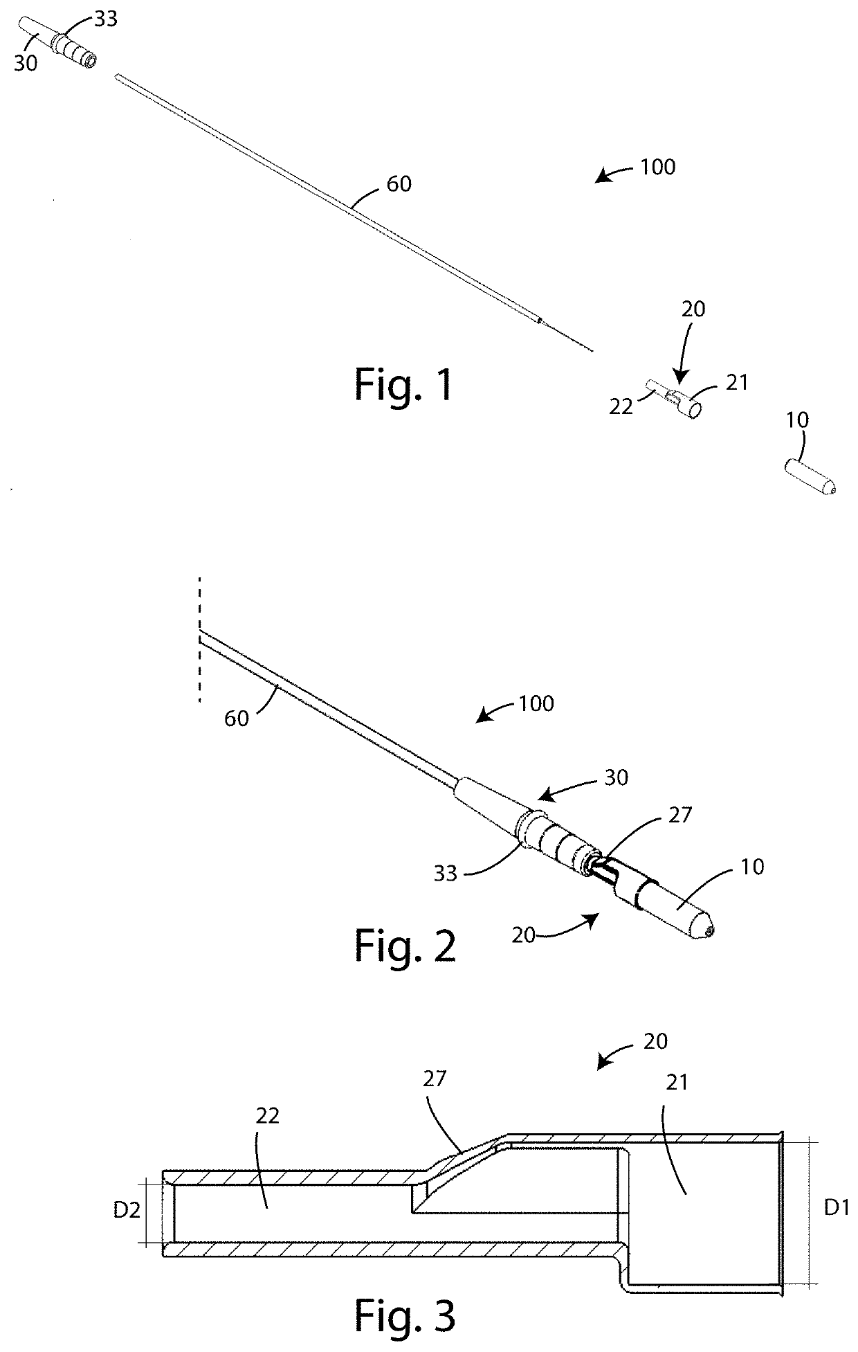
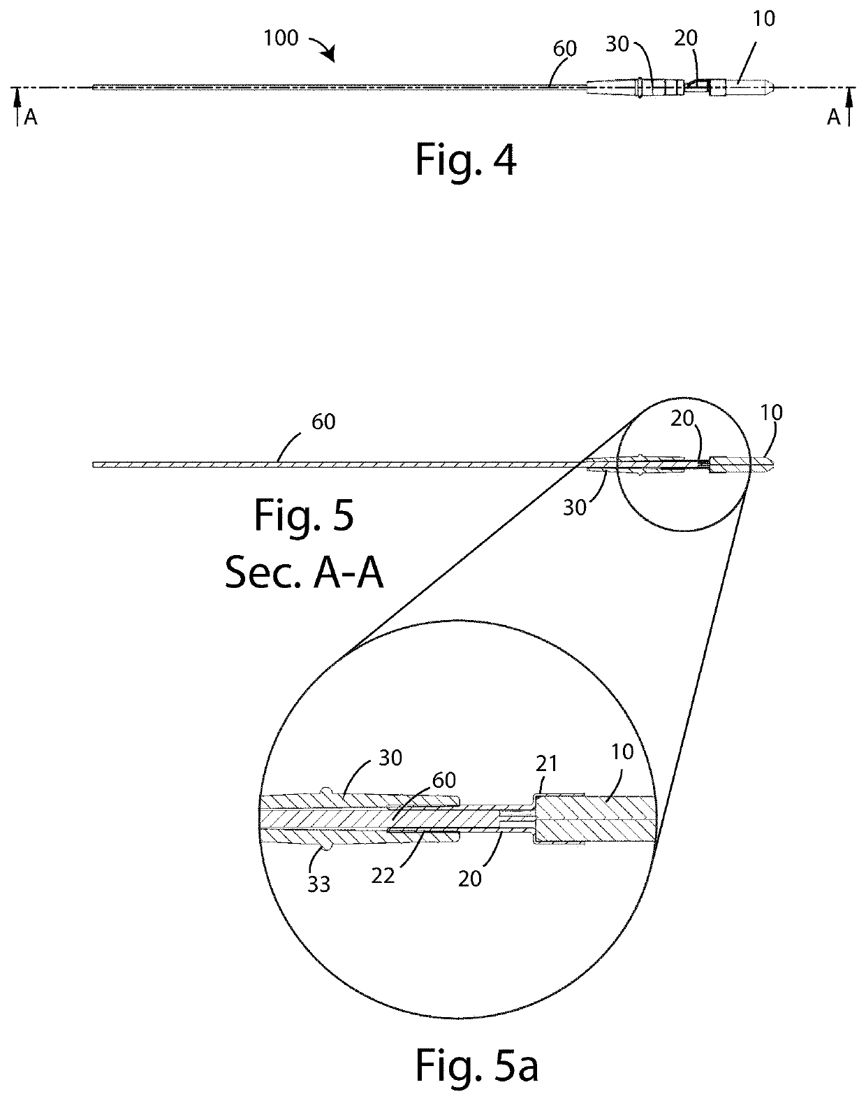
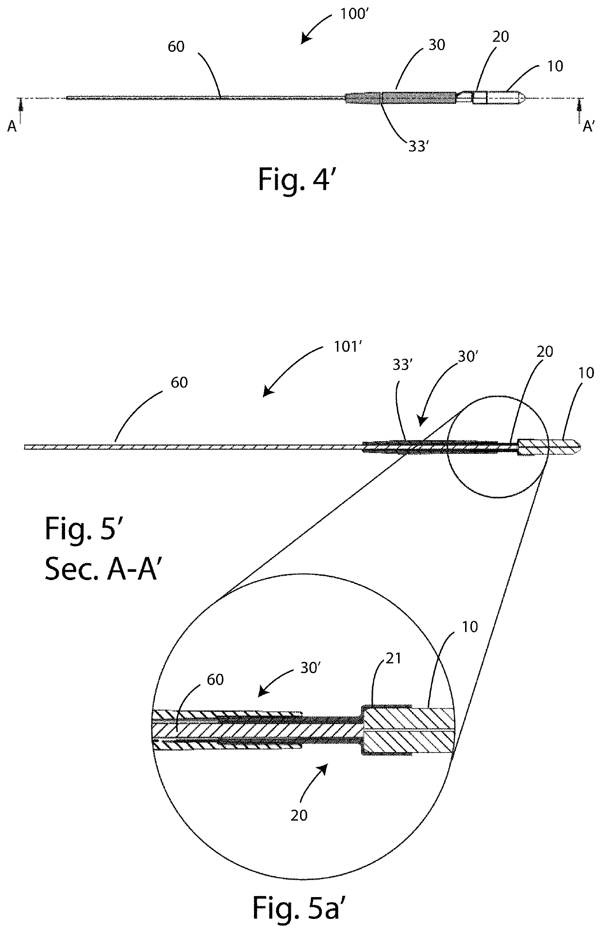
[0063]With reference to the figures, a connector device for optical fiber according to a first preferred embodiment of the invention is denoted as a whole with 100. A further embodiment of the device according to the invention will be denoted below with 101′.

[0064]The elements that the various embodiments have common will be denoted below with the same numbering.

[0065]The connector device 100, 100′ in this example is configured to allow, via an optical sleeve, for example a female-female connector, the transmission of an optical signal at one end of the fiber towards another fiber already connectorized.

[0066]The device 100, 100′ comprises a portion of optical fiber 60 having a ferrule 10 at at least one terminal end.

[0067]As shown in FIGS. 2 and 3, the device 100, 100′ described herein also provides a ferrule holder element 20.

[0068]The ferrule holder element 20, as shown in the enlargement of FIG. 3, is shaped like a double hollow cup comprising a first cup 21, having an internal d...


PUM


Abstract

The present disclosure relates to a connector device for optical fiber configured to allow the transmission of an optical signal at a terminal end of the fiber in a cabling condition. The device comprises a portion of optical fiber having a ferrule at at least one terminal end, a ferrule holder element and a protective element for the optical fiber. The overall configuration is such that the connector device has small radial and longitudinal dimensions which, in an operating condition, allow rapid movement within wiring cables or tubular ducts, for example cable ducts, pipes, conduits etc., which due to their sizes, hinder the passage of standard connectors of known type.

Description

INCORPORATION BY REFERENCE TO ANY PRIORITY APPLICATIONS[0001]This application is the U.S. National Phase of International Application PCT / IT2020 / 050088, filed Apr. 6, 2020, which claims the benefit of priority to Italian Application No. 102019000005080, filed on Apr. 4, 2019, the disclosures of each of which are hereby incorporated by reference in their entireties. Any and all applications for which a foreign or domestic priority claim is identified in the Application Data Sheet as filed with the present application are hereby incorporated by reference under 37 CFR 1.57.BACKGROUNDField[0002]The present invention relates to a connector device for optical fiber, i.e. a device for terminating optical fiber cables that require connection and / or disconnection.Description of the Related Art[0003]The optical fiber cables include a central optical fiber in glass, or plastic material, suitable for transmitting the light signal, an internal protective sheath in Nylon, Kevlar fibers, which are...

Claims


Application Information

Patent Timeline
IPC IPC(8): G02B6/44G02B6/50G02B6/38
CPCG02B6/4463G02B6/3847G02B6/508G02B6/3851G02B6/3871G02B6/50
Inventor PUGLIESE, GIOVANNIVENTRELLA, ALFREDO
Owner TELECOM & SECURITY SRL
Learn More