
Power supply system

a power supply system and power supply technology, applied in the field of power supply systems, can solve the problems of increasing the chance of not being able to exhibit the output performance of the second battery, the power capable of being outputted from the first battery becoming lower, and the second battery not being able to sufficiently exhibit the output performance. , to achieve the effect of reducing the number of power supply changes, reducing the chance of power supply failure, and reducing the number of power supply failures

Pending Publication Date: 2022-06-09
HONDA MOTOR CO LTD
View PDF0 Cites 0 Cited by
  • Summary
  • Abstract
  • Description
  • Claims
  • Application Information

AI Technical Summary

Benefits of technology

The present invention is a power supply system that allows for efficient use of electrical storage devices. The control device of the system allows for power path control to supply power from one device to another, based on their remaining capacity. The control device also prioritizes the use of the device with higher regeneration capacity, ensuring effective use of the stored energy. Additionally, the control device regulates the charging and discharging of the devices to maintain optimal performance and recover regeneration power. Overall, the power supply system improves the efficiency and performance of the power supply system.

Problems solved by technology

However, there is a tendency of the power capable of being outputted from the first battery becoming lower as the charge rate of the first battery declines.
For this reason, if the charge rate of the second battery is not sufficient when output from the second battery is requested, the second battery cannot sufficiently exhibit the output performance thereof.
In other words, if the charge rate of the first battery declines, the chance of no longer being able to sufficiently exhibit the output performance of the second battery also increases.

Method used


Image

  • Power supply system
  • Power supply system
  • Power supply system

Examples


Embodiment Construction

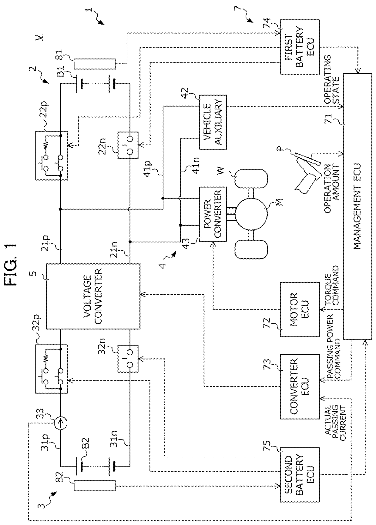
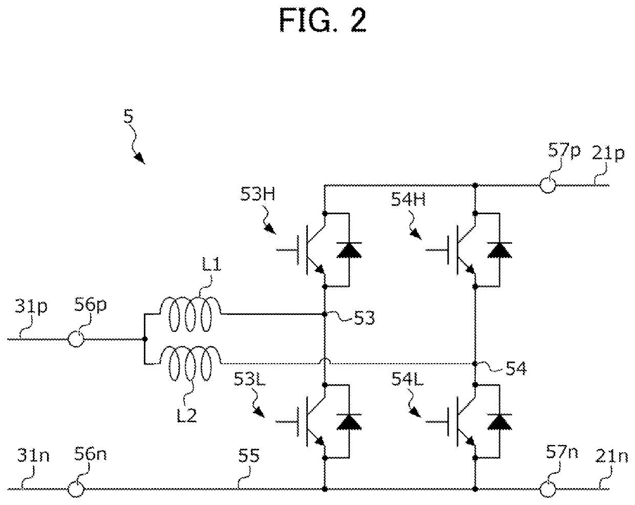
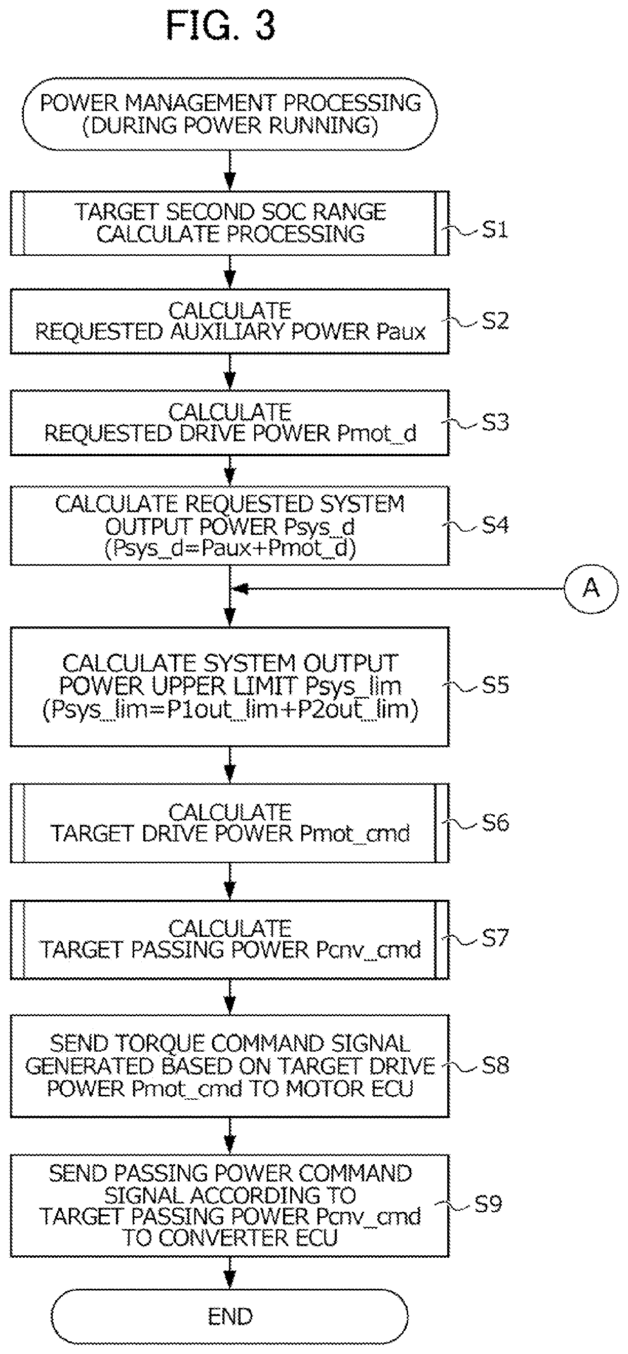
[0034]Hereinafter, an embodiment of the present invention will be explained while referencing the drawings. FIG. 1 is a view showing the configuration of an electric vehicle V (hereinafter simply referred to as “vehicle”) equipped with a power supply system 1 according to the present embodiment.

[0035]The vehicle V includes drive wheels W, a drive motor M serving as a rotary electrical machine coupled to these drive wheels W; and a power supply system 1 which performs transferring of power between this drive motor M and a first battery B1 and second battery B2 described later. It should be noted that the present embodiment explains an example in which the vehicle V accelerates and decelerates by the motive power generated mainly by the drive motor M; however, the present invention is not to be limited thereto. The vehicle V may be established as a so-called hybrid vehicle equipped with the drive motor M and an engine as the motive power generation source.

[0036]The drive motor M is co...


PUM

PropertyMeasurementUnit
weight densityaaaaaaaaaa
energy weight densityaaaaaaaaaa
electrical energyaaaaaaaaaa

Abstract

A power supply system includes a load circuit containing a drive motor coupled to a drive wheel; a first battery of capacity type; a second battery of output type; a power circuit connecting the load circuit, first battery and second battery; and a management ECU which controls flow of power between the first and second batteries and the drive motor, as well as flow of power from the first battery to the second battery, by operating the power circuit. The management ECU, in the case of a second SOC corresponding to the charge rate of the second battery being less than a second SOC lower limit value A, permits execution of power path control to supply the power outputted from the first battery to the second battery, and sets the second SOC lower limit value A to a greater value as the first SOC of the first battery becomes smaller.

Description

[0001]This application is based on and claims the benefit of priority from Japanese Patent Application No. 2020-201116, filed on 3 Dec. 2020, the content of which is incorporated herein by reference.BACKGROUND OF THE INVENTIONField of the Invention[0002]The present invention relates to a power supply system. In more detail, it relates to a power supply system of a vehicle equipped with two electrical storage devices having different characteristics.Related Art[0003]In recent years, development has been active in electric vehicles such as electric transport equipment equipped with a drive motor as a power generation source, and hybrid vehicles equipped with a drive motor and internal combustion engine as power generation sources. In such electric vehicles, an electrical storage device (battery, and capacitor etc.) for supplying electrical energy to the drive motor is also built in. In addition, in recent years, a vehicle equipped with a plurality of electrical storage devices having ...

Claims


Application Information

Patent Timeline
Patent Type & Authority Applications(United States)
IPC IPC(8): B60L3/00B60L50/51B60L58/13H01M10/44H02J7/00
CPCB60L3/0046B60L50/51B60L58/13B60L7/10H02J7/007B60L2210/10H01M2220/20H01M10/441B60L50/60B60L58/10B60L58/12B60L53/22B60L50/40Y02E60/10Y02T90/14B60L58/20B60L58/22B60L15/2045B60L7/14B60L7/16B60L2240/429B60L2240/547B60L2240/549H02J7/342H02J7/0068H02J2310/48H02J7/00712H02J7/0048
Inventor SUZUKI, KENTAOGUMA, HIROKAZU
Owner HONDA MOTOR CO LTD
Learn More