
Motion control system and method

a technology of motion control and control system, applied in the direction of electric programme control, program control, instruments, etc., can solve the problems of machine tools in the factory being difficult to receive signals, overwork of operators, and machine tools that cannot operate normally, so as to avoid damage to machined products

Active Publication Date: 2022-06-16
IND TECH RES INST
View PDF0 Cites 0 Cited by
  • Summary
  • Abstract
  • Description
  • Claims
  • Application Information

AI Technical Summary

Benefits of technology

This patent describes a motion control system and method for adjusting the speed of a machine tool during remote control. The system includes a buffer that stores machining commands sent from a first controller, allowing for quick adjustments based on the communication state. This prevents abnormal mechanical conditions, sudden shutdowns, and damage to machined products when poor communication occurs between the first and second controllers. The technical effect is improved stability and control during remote machine tool operation.

Problems solved by technology

However, during operation of a conventional machine tool, an operator has to stay at the location of the machine tool (e.g., a control center of the factory) to control the operation of the machine tool.
As such, a lot of human resources are needed in the factory, and the operator cannot leave the factory at any time, which may cause the problem of overwork of the operator.
However, since the conventional CNC wireless control system uses a network mechanism for signal transmission, if poor communication occurs in the network, it may become difficult for the machine tools in the factory to receive signals.
Consequently, the machine tools cannot operate normally.
For example, problems such as abnormal mechanical conditions (e.g., cutting tool jitter, etc.), sudden shutdown or other unexpected motion may prevent the machine tools from effectively performing machining operations and cause defects in machined products.
Hence, the defective products have to be scrapped.
Therefore, how to prevent the machine tools from being unable to operate normally due to poor communication has become an urgent issue in the art.

Method used


Image

  • Motion control system and method
  • Motion control system and method
  • Motion control system and method

Examples


Embodiment Construction

[0027]The following illustrative embodiments are provided to illustrate the present disclosure, these and other advantages and effects can be apparent to those in the art after reading this specification.

[0028]It should be noted that all the drawings are not intended to limit the present disclosure. Various modifications and variations can be made without departing from the spirit of the present disclosure. Further, terms such as “first,”“second,”“on,”“a,” etc., are merely for illustrative purposes and should not be construed to limit the scope of the present disclosure.

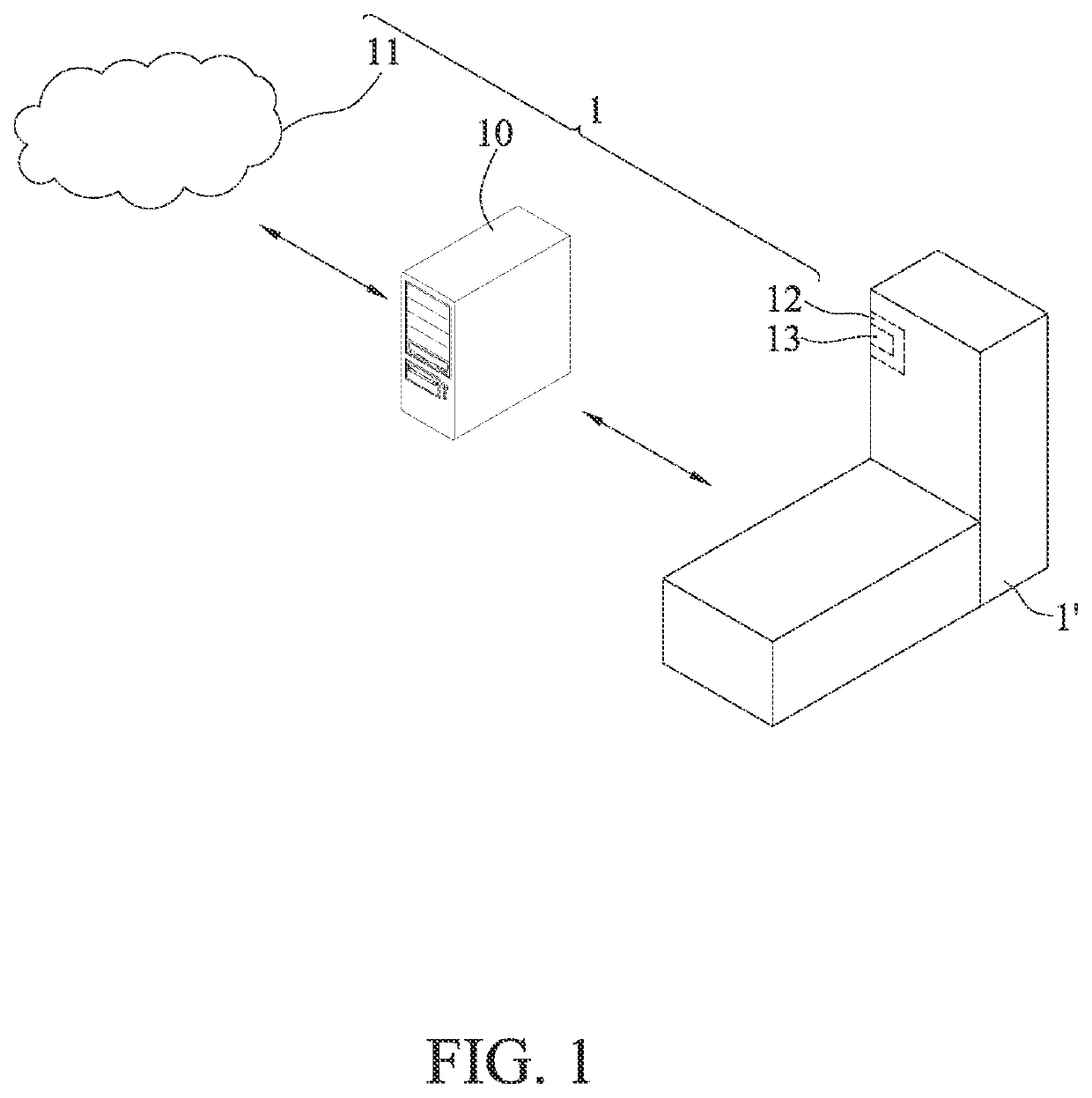
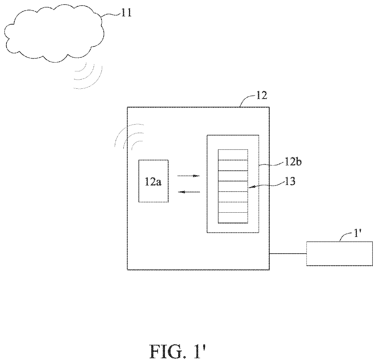
[0029]FIG. 1 is a schematic diagram showing the configuration of a motion control system 1 according to the present disclosure. Referring to FIG. 1, the motion control system 1 has a first controller 11, at least one second controller 12 and a buffer 13 connected to the second controller 12. However, the present disclosure does not limit the integration, replacement, or addition / reduction of the various components of...


PUM


Abstract

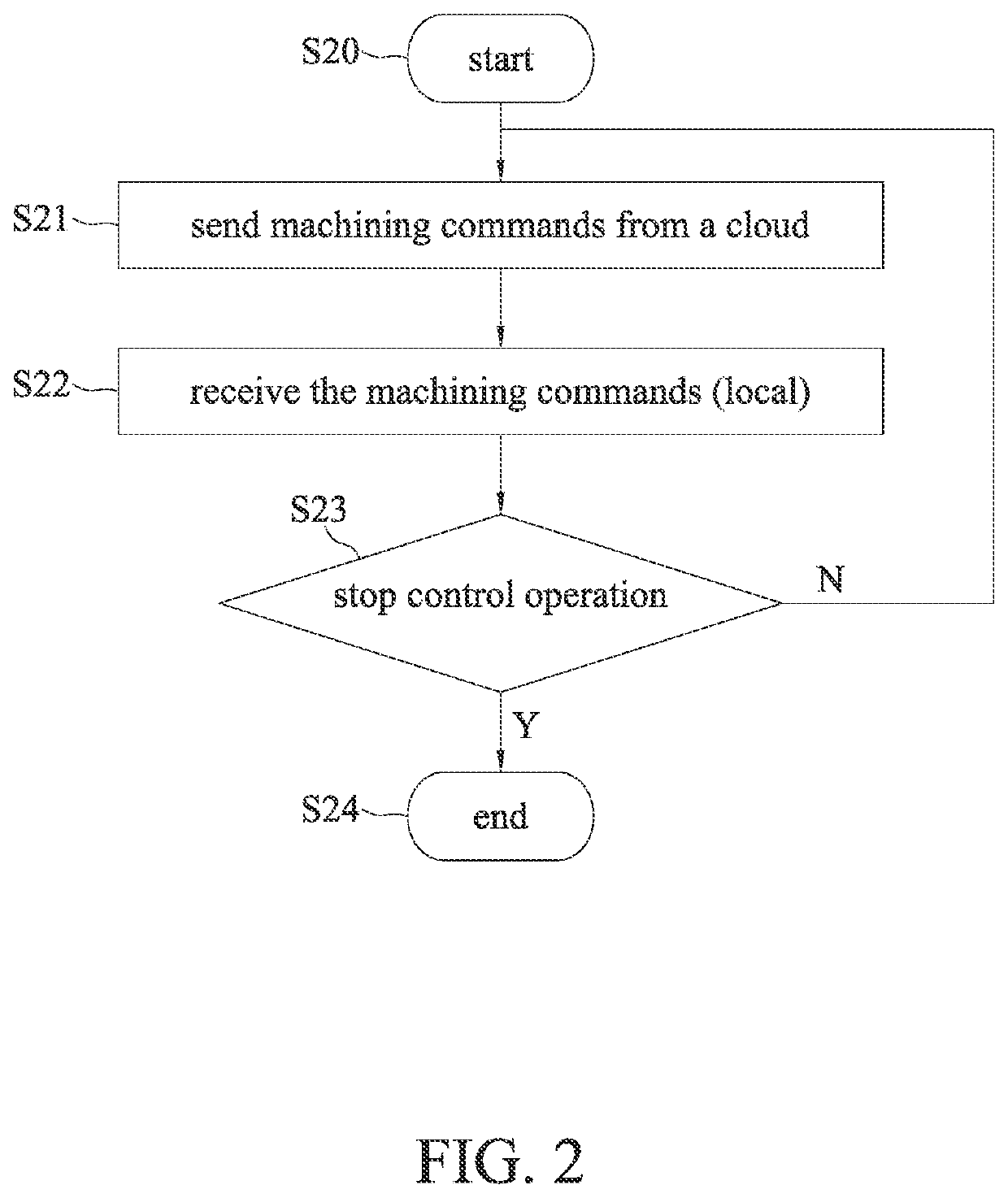
A motion control system and a motion control method are provided. The motion control method includes: sending a plurality of machining commands to a second controller by a first controller at a cloud; storing the plurality of machining commands in a buffer by the second controller; and operating the machine tool according to the plurality of machining commands stored in the buffer. As such, when poor communication occurs between the first controller and the second controller, the second controller causes the buffer to send a deceleration command to the machine tool so as to cause the machine tool to operate at a reduced speed, thereby avoiding unexpected motion such as sudden shutdown of the machine tool and damage to machined products.

Description

CROSS-REFERENCE TO RELATED APPLICATIONS[0001]This application claims priority to Taiwan Application Serial No. 109143952, filed on Dec. 11, 2020. The entirety of the above-mentioned patent application is hereby incorporated by reference herein and made a part of this specification.BACKGROUND1. Technical Field[0002]The present disclosure relates to control systems and methods, and more particularly, to a motion control system and method having a remote control mechanism.2. Description of Related Art[0003]Along with the rapid development of machine tool automation, performing machining operations by inputting related parameters has become a mainstream. Therefore, computer numerical control (CNC) technology has been widely applied in machine tools for machining operations. Meanwhile, a machine tool generally goes through an adjustment process before leaving the factory. Through adjustment of related parameters, the machine tool can meet certain performance indicators and hence meet spe...

Claims


Application Information

Patent Timeline
Patent Type & Authority Applications(United States)
IPC IPC(8): B23Q15/08
CPCB23Q15/08B23Q2717/006G05B19/4185G05B19/41885G05B19/4163G05B2219/31241G05B2219/23298G05B19/416
Inventor CHENG, CHIH-PINGCHEN, CHIN-HUIHO, MING-CHUNLUO, TZUO-LIANGCHANG, WAN-KUNLIANG, SHUO-PENG
Owner IND TECH RES INST
Learn More