Wavefront correction for beam shaping

a beam shaping and wavefront correction technology, applied in the field of wavefront correction for beam shaping, can solve the problems of adding to the wavefront non-uniformity, adding to the distortion of the optical beam, and the optical beam received back from the object is typically distorted, so as to minimize the supporting structure, minimize the mirror area, and the effect of slight til

Pending Publication Date: 2022-06-23
BEIJING VOYAGER TECH CO LTD
View PDF0 Cites 2 Cited by
  • Summary
  • Abstract
  • Description
  • Claims
  • Application Information

AI Technical Summary

Benefits of technology

[0012]In some embodiments, each MEMS micro mirror is an electrostatic force micro mirror with a mirror body and at least two electrodes below a mirror body. An electrostatic force micro mirror is a design which maximizes the mirror area and minimizes supporting structure. This allows reflecting, at the desired tilt angle, most of the light hitting that mirror, which is considered a single pixel. With a large number of pixels, only a slight tilt, and thus a slight amount of electrostatic force, need be applied, minimizing the power requirement.
[0013]In one embodiment, the electrostatic MEMS micro mirror has a pair of anchors at diagonal corners that are connected, via a spring, to the mirror body, enabling one directional wavefront correction along a first diagonal axis. For a micro tilting mirror with the same area size, a diagonal axis based tilting mirror has a smaller moment of inertia since more of the mirror mass is closer to the axis than for a perpendicular axis. The smaller moment of inertia makes the mirror more stable and easier to be actuated. The two electrodes are connected to first and second control voltage sources, and the mirror body is connected to ground. The voltage sources are controlled to activate one or the other, to tilt the mirror body with electrostatic force generated by the voltage difference between the electrode and the mirror body

Problems solved by technology

In a scanning flash LiDAR system, the optical beam received back from the object is typically distorted for various reasons.
For example, the initial divergence from the laser source adds to the beam, causing it to be mis-collimated.
Air density non-uniformity along the optical path also adds to the wavefront non-uniformity.
Receiving lens aberrations add to the distortion of the optical beam spot focused on the focal plane.
All of these beam distortions increase the effective optical spot size on the focal plane of the detector, causing the focused beam to be more spread out across the focal plane, therefore reducing the effective optical intensity per unit area.
These optics can introduce wavefront distortions, in particular around the edges.
Such distortions introduce noise in the system, making it more difficult to distinguish the received pulse from surrounding noise, and thus making the detection of objects by LiDAR more difficult.

Method used


Image

  • Wavefront correction for beam shaping
  • Wavefront correction for beam shaping
  • Wavefront correction for beam shaping

Examples


Embodiment Construction

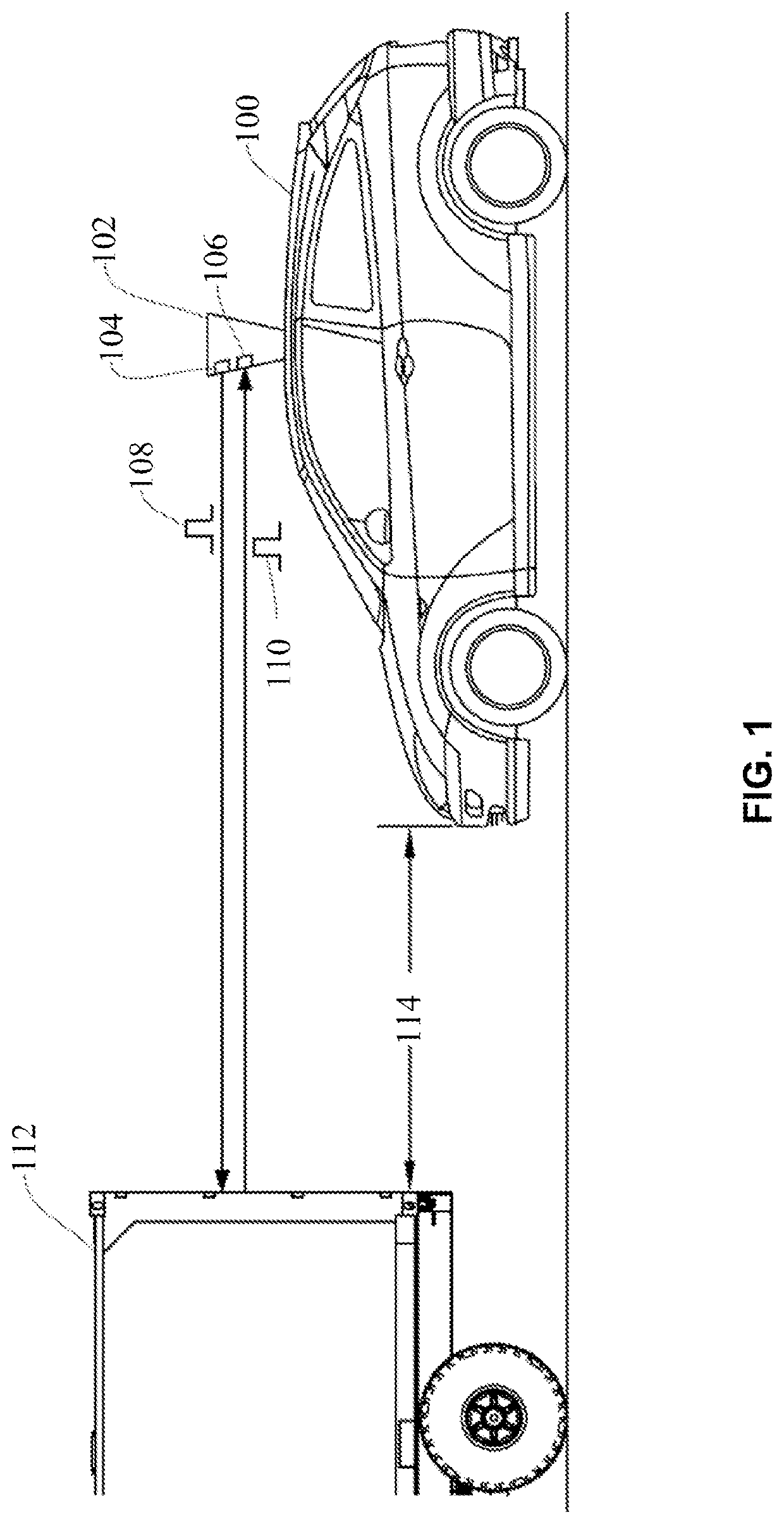
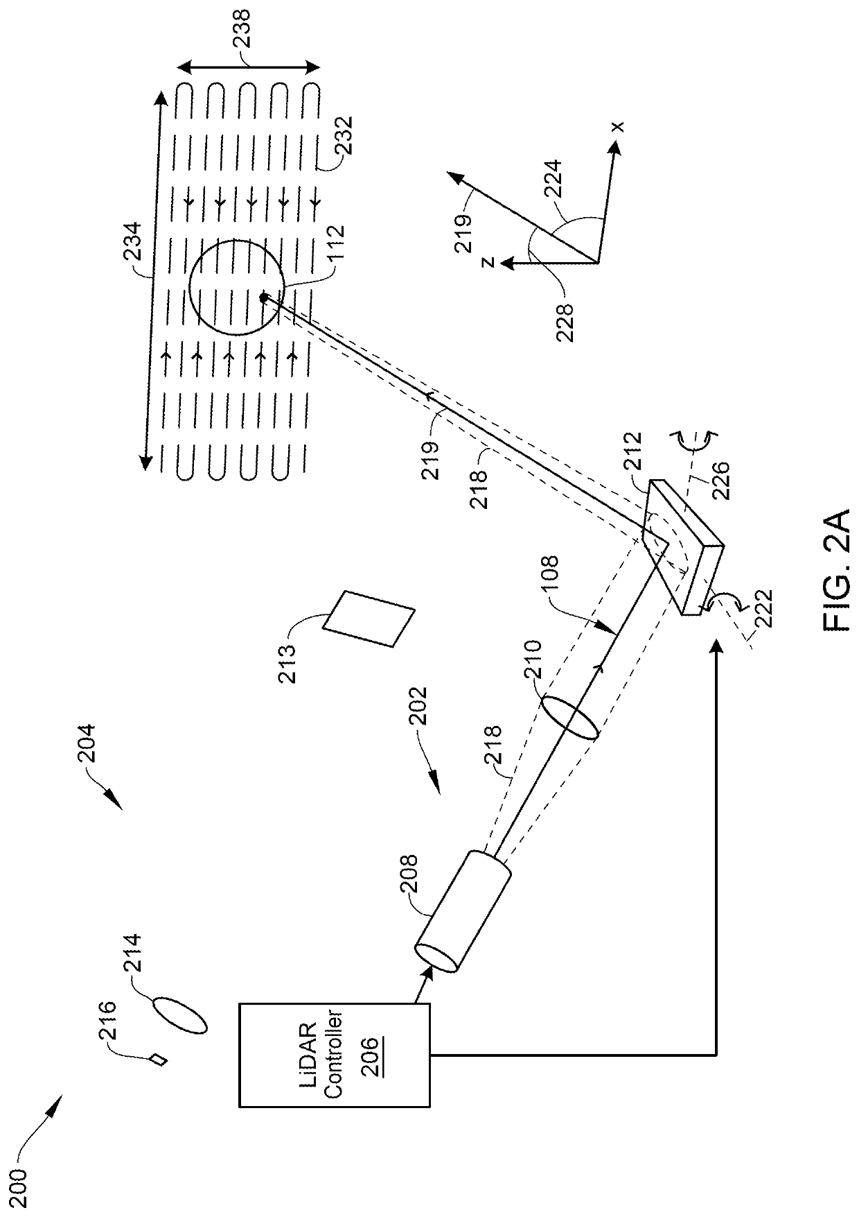
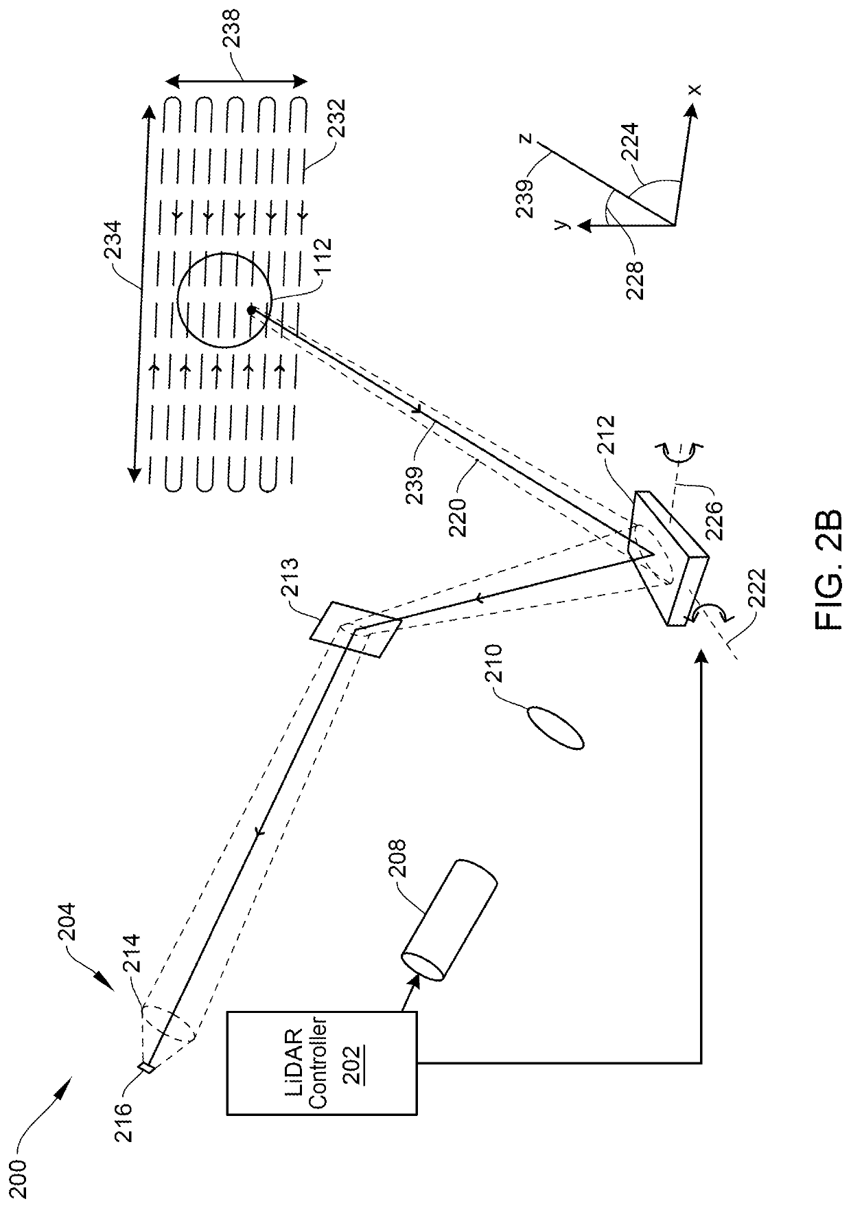
[0030]Aspects of the present disclosure relate generally to correcting for wavefront distortions, and more particularly to LiDAR systems, according to certain embodiments.

[0031]In the following description, various examples of a wavefront correction feedback system and MEMS-based micro mirror structures and are described. For purposes of explanation, specific configurations and details are set forth in order to provide a thorough understanding of the embodiments. However, it will be apparent to one skilled in the art that certain embodiments may be practiced or implemented without every detail disclosed. Furthermore, well-known features may be omitted or simplified in order to prevent any obfuscation of the novel features described herein.

[0032]The following high level summary is intended to provide a basic understanding of some of the novel innovations depicted in the figures and presented in the corresponding descriptions provided below. Aspects of the invention relate to correcti...


PUM


Abstract

An apparatus for detecting an incoming laser beam with a photodetector is described. A beam splitter is mounted to receive the incoming laser beam after correction by a wavefront corrector. The beam splitter directs most of the incoming laser beam to the photodetector, but diverts a small portion of the incoming laser beam to a wavefront sensor. A feedback control circuit is configured to control the wavefront corrector to at least partially correct for wavefront distortions detected by the wavefront sensor.

Description

BACKGROUND OF THE INVENTION[0001]Unless otherwise indicated herein, the materials described in this section are not prior art to the claims in this application and are not admitted to be prior art by inclusion in this section. In particular, disparate technologies are discussed that it would not be obvious to discuss together absent the teachings of the present invention.[0002]Modern vehicles are often equipped with sensors designed to detect objects and landscape features around the vehicle in real-time to enable technologies such as lane change assistance, collision avoidance, and autonomous driving. Some commonly used sensors include image sensors (e.g., infrared or visible light cameras), acoustic sensors (e.g., ultrasonic parking sensors), radio detection and ranging (RADAR) sensors, magnetometers (e.g., passive sensing of large ferrous objects, such as trucks, cars, or rail cars), and light detection and ranging (LiDAR) sensors.[0003]A LiDAR system typically uses a light sourc...

Claims


Application Information

Patent Timeline
Patent Type & Authority Applications(United States)
IPC IPC(8): G01S7/497G01S7/4863G01S7/481
CPCG01S7/497G01S7/4863G01S17/931G01S7/4816G01S7/4817G01S7/4814G01S17/89
Inventor LU, YUEWANG, YOUMIN
Owner BEIJING VOYAGER TECH CO LTD
Why Eureka
Try Eureka