Optimised heat exchange system of a turbomachine

Pending Publication Date: 2022-06-30
SAFRAN
View PDF0 Cites 0 Cited by
  • Summary
  • Abstract
  • Description
  • Claims
  • Application Information

AI Technical Summary

Benefits of technology

The present invention provides a heat exchange system for turbomachines that optimizes heat exchanges by controlling the flow rate of air passing through the system, while avoiding pressure drops and minimizing disturbance to the air flow. The system includes a heat exchanger with a support wall and a plurality of fins. A cover is connected upstream and downstream from the fins, guiding and slowing down the air flow entering the heat exchanger, and accelerating the air flow exiting the heat exchanger. The cover has an aerodynamic profile that improves the system's integration into the air flow, particularly the secondary air flow. The system ensures optimal aerothermal performance and minimizes pressure drops, achieving efficient heat exchanges and reducing the need for larger equipment.

Problems solved by technology

In fact, when this heat exchange system is installed in a turbomachine and in particular in a secondary vein, the flow of the secondary air flow is very turbulent, which corresponds to a high flow Reynolds number that degrades the aerothermal performance of the heat exchanger.

Method used


Image

  • Optimised heat exchange system of a turbomachine
  • Optimised heat exchange system of a turbomachine
  • Optimised heat exchange system of a turbomachine

Examples


Embodiment Construction

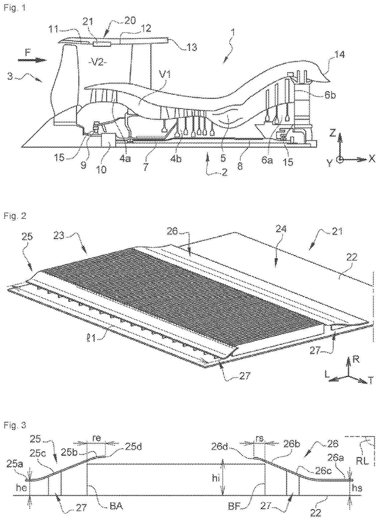
[0057]FIG. 1 shows an axial cross-sectional view of a turbomachine of longitudinal axis X to which the invention applies. The turbomachine shown is a double-flow turbomachine 1 intended to be mounted on an aircraft. Of course, the invention is not limited to this type of turbomachine.

[0058]This double-flow turbomachine 1 generally comprises a gas generator 2 upstream of which is mounted a fan or fan module 3.

[0059]In the present invention, the terms “upstream” and “downstream” are defined in relation to the flow of gases in the turbomachine and here along the longitudinal axis X.

[0060]The gas generator 2 comprises a gas compressor assembly (here comprising a low pressure compressor 4a and a high pressure compressor 4b), a combustion chamber 5 and a turbine assembly (here comprising a high pressure turbine 6a and a low pressure turbine 6b). Typically the turbomachine comprises a low pressure shaft 7 which connects the low pressure compressor and the low pressure turbine to form a low...


PUM


Abstract

A heat exchange system of a turbomachine, includes a heat exchanger including a support wall, a plurality of fins each extending in a radial direction from a radially outer surface of the support wall, and a cover covering the fins, wherein the cover is connected, upstream in the direction of flow of the air flow, to a first profiled wall, and downstream to a second profiled wall, the first profiled wall being arranged upstream from the fins and configured to guide and slow down the flow of air entering the heat exchanger through the fins, and the second profiled wall being arranged downstream from the fins and configured so as to accelerate the flow of air leaving the heat exchanger, wherein the cover has an at least partially curvilinear aerodynamic profile and an outer peripheral surface having surface continuity with radially outer surfaces of the first and second walls.

Description

TECHNICAL FIELD OF THE INVENTION[0001]The present invention relates to the general field of aeronautic. It aims in particular at a heat exchange system for a turbomachine.BACKGROUND[0002]A turbomachine, in particular of an aircraft, comprises various members and / or equipment that need to be lubricated and / or cooled, such as rolling bearings and gears. The heat released by these components, which can be very high depending on the power of the member and / or the equipment, is transported by a fluid and evacuated towards cold sources available in the aircraft.[0003]It is known to equip the turbomachine with one or more heat exchange systems to carry out the heat exchange between the fluid (typically oil) and the cold source (air, fuel, etc.). There are even different types of heat exchange systems, such as for example the fuel / oil heat exchangers, generally known by the acronym FCOC (Fuel Cooled Oil Cooler) and the air / oil heat exchangers, known by the acronym ACOC (Air-Cooled Oil Coole...

Claims


Application Information

Patent Timeline
IPC IPC(8): F02C7/18F28D7/08F28F13/08
CPCF02C7/18F28D2021/0021F28F13/08F28D7/085F02C7/14F02C7/06F28D7/005F28D7/06F28D2021/0049F28F1/24F02K3/06F05D2260/98F05D2260/4031F05D2260/40311F05D2260/22141Y02T50/60
Inventor TOUBIANA, EPHRAÏMMAALOUF, SAMERTANG, ETIENNE YUNG
Owner SAFRAN
Why Eureka
Try Eureka