
Contact matrix for grounding a ceramic component during electrical discharge machining

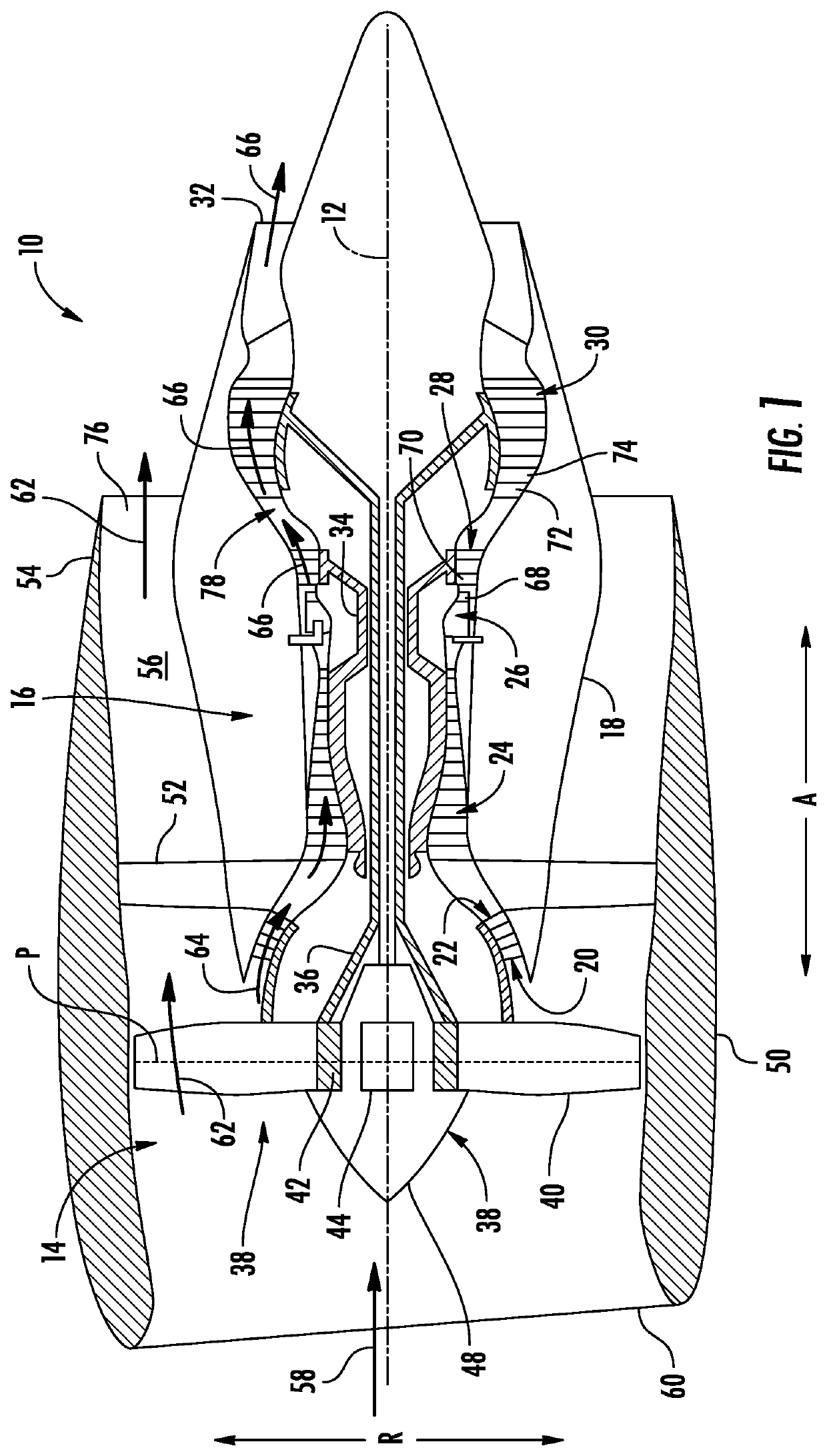
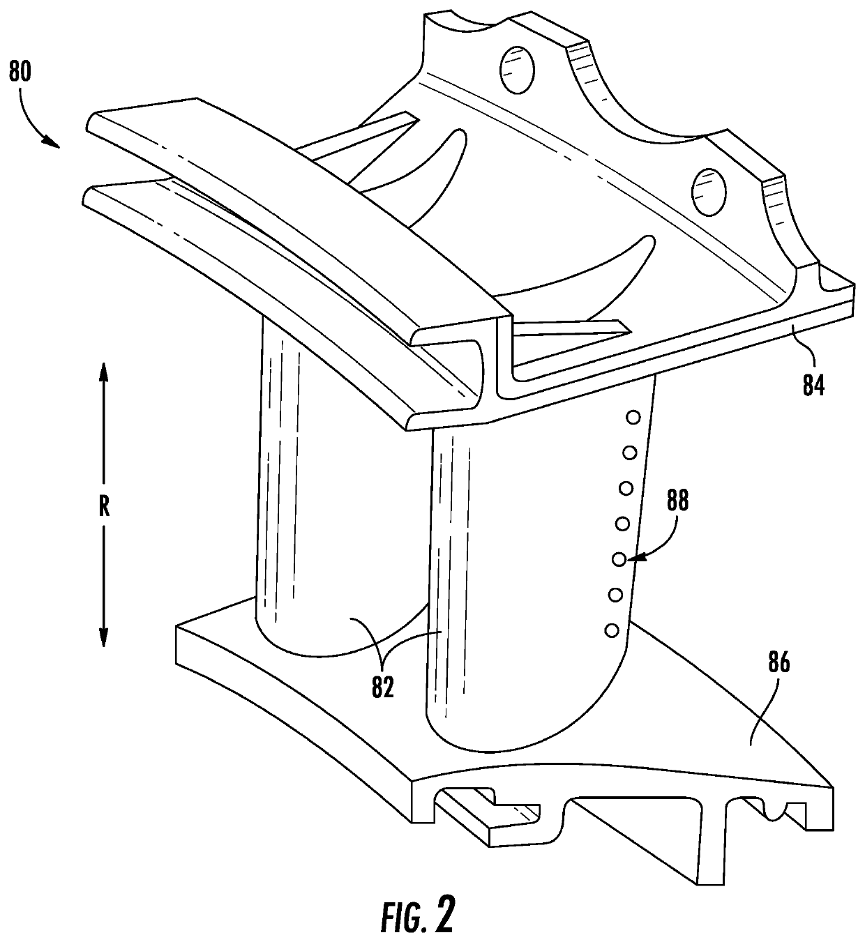
a ceramic component and contact matrix technology, applied in the direction of machines/engines, manufacturing tools, connection contact member materials, etc., can solve the problems of inefficient and/or effective electrical grounding of cmc components during edm, inability to effectively ground components in an efficient and/or effective manner, and inability to achieve the effect of edm,

Pending Publication Date: 2022-07-07
GENERAL ELECTRIC CO
View PDF0 Cites 0 Cited by
  • Summary
  • Abstract
  • Description
  • Claims
  • Application Information

AI Technical Summary

Benefits of technology

This patent describes a new invention and its benefits. The technical effects of this invention will be introduced partially in the description, but may also be found by practicing the invention.

Problems solved by technology

One challenge with drilling features in CMC components via EDM, or ceramic components generally, is that such components are not typically electrically grounded in an efficient and / or effective manner.
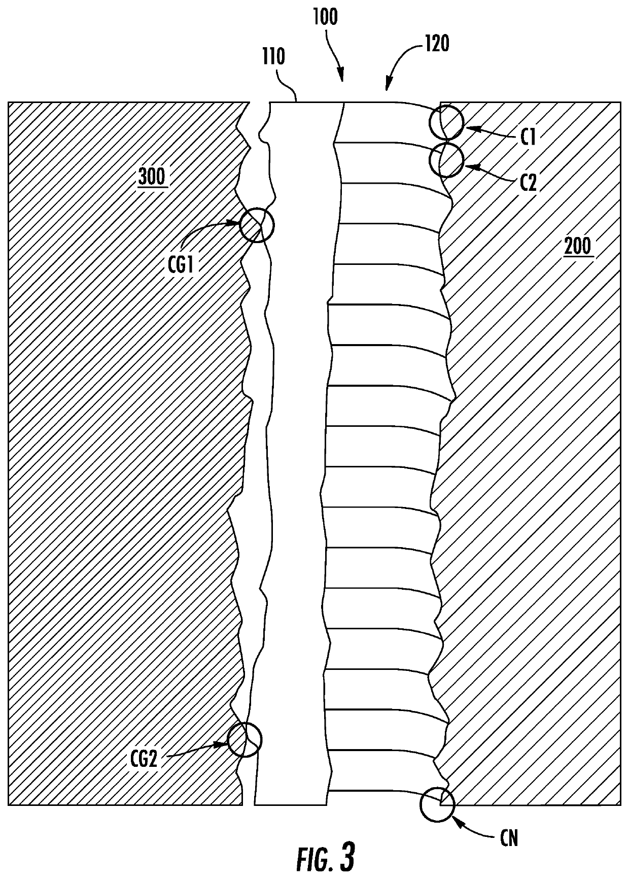
Due to the surface irregularity of the metallic structure and the CMC component, many times only a limited number of contact points are made between the rigid CMC component and the rigid metallic grounding structure.
Due to the surface potential or Schottky barrier, the electrical resistance at these contact points can be considerable, which creates bottlenecks of electrical current that obstructs or even fails the electrical grounding process by point overheating and / or arcing.
Inefficient and / or ineffective electrical grounding of a CMC component during EDM is undesirable.
For instance, ineffective electrical grounding can result in pitting at the grounding contact points.

Method used


Image

  • Contact matrix for grounding a ceramic component during electrical discharge machining
  • Contact matrix for grounding a ceramic component during electrical discharge machining
  • Contact matrix for grounding a ceramic component during electrical discharge machining

Examples


Embodiment Construction

[0024]Reference will now be made in detail to present embodiments of the invention, one or more examples of which are illustrated in the accompanying drawings. The detailed description uses numerical and letter designations to refer to features in the drawings. Like or similar designations in the drawings and description have been used to refer to like or similar parts of the invention. As used herein, the terms “first,”“second,” and “third” may be used interchangeably to distinguish one component from another and are not intended to signify location or importance of the individual components. The terms “upstream” and “downstream” refer to the relative direction with respect to fluid flow in a fluid pathway. For example, “upstream” refers to the direction from which the fluid flows and “downstream” refers to the direction to which the fluid flows.

[0025]As used herein, a “ceramic component” is a component formed of ceramic-based materials. Ceramic-based materials encompass both homog...


PUM

PropertyMeasurementUnit
Electrical conductivityaaaaaaaaaa
Flexibilityaaaaaaaaaa
Conductionaaaaaaaaaa

Abstract

Methods of Electrical Discharge Machining (EDM) ceramic components are provided. In one aspect, a method includes electrical discharge machining a ceramic component, such as a Ceramic Matrix Composite (CMC) component. The ceramic component is electrical discharge machined while a contact matrix is positioned so that electrically conductive compliant and pressurized contacts of the contact matrix engage the ceramic component and so that an electrically conductive member of the contact matrix is in electrical conduction to a grounding structure.

Description

FIELD[0001]The present subject matter relates generally to electrical discharge machining ceramic components, such as ceramic matrix composite components.BACKGROUND[0002]Electrical Discharge Machining (EDM) is sometimes used to machine features in ceramic components, such as Ceramic Matrix Composite (CMC) components for gas turbine engines. For example, EDM can be used to drill cooling holes in CMC high-pressure turbine nozzles. One challenge with drilling features in CMC components via EDM, or ceramic components generally, is that such components are not typically electrically grounded in an efficient and / or effective manner. Typically, a metallic fixture or other metallic structure is used to electrically ground CMC components during EDM. Due to the surface irregularity of the metallic structure and the CMC component, many times only a limited number of contact points are made between the rigid CMC component and the rigid metallic grounding structure. Due to the surface potential ...

Claims


Application Information

Patent Timeline
IPC IPC(8): B23H1/04
CPCB23H1/04H01R43/00H01R4/64F02C7/00B23H9/10
Inventor THIEL, JACOB GREGORYLUO, YUEFENGHANNA, ALLISON MICHELLEMYERS, CALEB DEWAYNE
Owner GENERAL ELECTRIC CO
Learn More