Driving system for core drilling rig

a driving system and core drilling technology, applied in the direction of drilling rods, drilling pipes, borehole/well accessories, etc., can solve the problems of high temperature in the downhole and inability to use electrical equipmen

Pending Publication Date: 2022-07-07
SHENZHEN UNIV +1
View PDF0 Cites 2 Cited by
  • Summary
  • Abstract
  • Description
  • Claims
  • Application Information

AI Technical Summary

Problems solved by technology

The downhole temperature is high, and

Method used


Image

  • Driving system for core drilling rig
  • Driving system for core drilling rig
  • Driving system for core drilling rig

Examples


Embodiment Construction

[0039]In order to make the objectives, technical solutions, and advantages of the present invention clearer, the present invention will be further illustrated hereinafter by combing with the attached Figures.

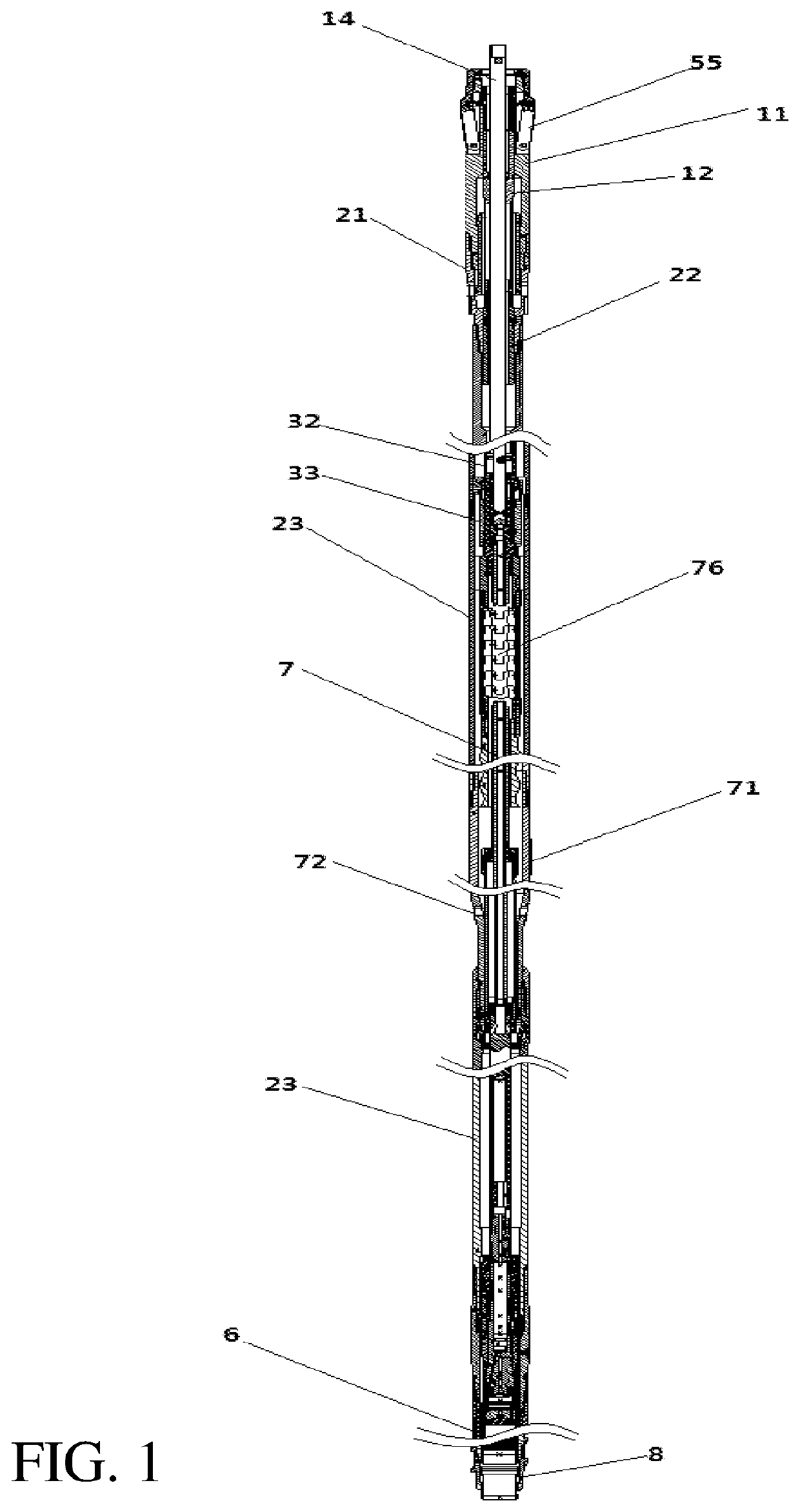
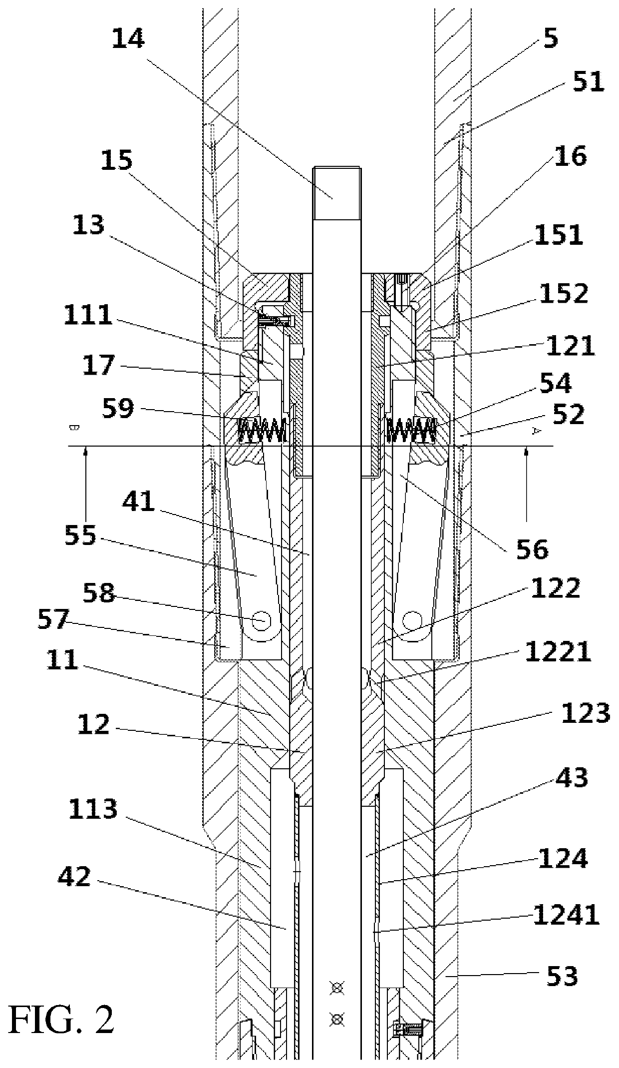
[0040]As shown in FIGS. 1-7, the core drilling rig includes a dental drill 5 and a coring system. The dental drill 5 is hollow, and the coring system is in the dental drill 5, and the outer wall of the coring system is in a sliding fit with the inner wall of the dental drill 5. The dental drill 5 comprises a first drill tube 51, a second drill tube 52, and a third drill tube 53 from back to front. The first drill tube 51 and the second drill tube 52 are detachably connected, and the second drill tube 52 and the third drill tube 53 are detachably connected. The front end of the first drill tube 51 is a male end, and the rear end of the second drill tube 52 is a female end, while the front end is a male end. The rear end of the third drill tube 53 is a female end. The inner wall o...


PUM


Abstract

A driving system for a core drilling rig has a driving motor. The driving motor has an outer rotor and an inner stator, and mutually-matched convex ribs are provided on the inner wall of the outer rotor and the outer wall of the inner stator. The outer rotor and the inner stator are in clearance fit. A clearance between the outer rotor and the inner stator is a driving liquid channel. The length of the outer rotor is less than that of the inner stator. The outer rotor is provided between the front and rear ends of the inner stator. The outer rotor is connected to an outer cylinder. The rear end of the inner stator is connected to a coupling.

Description

TECHNICAL FIELD[0001]The present invention relates to a core drilling system, and especially to a driving system of core drilling rig.BACKGROUND ART[0002]In the process of oilfield exploration, rock core is the key material for discovering oil and gas reservoir, as well as studying stratum, source rock, reservoir rock, cap rock, structure, and so on. Through the observation and study of the core, the lithology, physical properties, as well as the occurrence and characteristics of oil, gas, and water can be directly understood. After the oilfield is put into development, it is necessary to further study and understand the reservoir sedimentary characteristics, reservoir physical properties, pore structure, wettability, relative permeability, lithofacies characteristics, reservoir physical simulation, and reservoir water flooding law through core. Understanding and mastering the water flooded characteristics of reservoirs in different development stages and water cut stages, and findi...

Claims


Application Information

Patent Timeline
IPC IPC(8): E21B23/04E21B4/02E21B4/18E21B21/10E21B25/00
CPCE21B23/0418E21B4/02E21B25/00E21B21/10E21B4/18E21B4/006E21B17/1078E21B17/18
Inventor GAO, MINGZHONGXIE, HEPINGCHEN, LINGGUO, JUNZHANG, ZHILONGZHANG, ZETIANLU, YIQIANGLI, CONGHE, ZHIQIANG
Owner SHENZHEN UNIV
Why Eureka
Try Eureka