

Rework device and rework method
a shingle cell module and rework device technology, applied in the field of rework devices and rework methods, can solve the problems of difficult operation, low yield of shingle cell equipment, and inability to use full shingle cell modules
- Summary
- Abstract
- Description
- Claims
- Application Information
AI Technical Summary
Benefits of technology
Problems solved by technology
Method used
Image

Examples
Embodiment Construction
[0036]As will be understood by one of ordinary skill in the art, the various features of the embodiments shown and described with respect to any one of the figures can be combined with the features shown in one or more other figures to produce other embodiments that are not explicitly shown or described. The combination of features shown provides a representative embodiment for a typical application. However, various combinations and modifications of the features are possible in accordance with the teachings of the present disclosure for a particular application or implementation.
[0037]In the present specification, the words “upper”, “lower”, “left”, “right” and the like are used for convenience only, and are not restrictive.
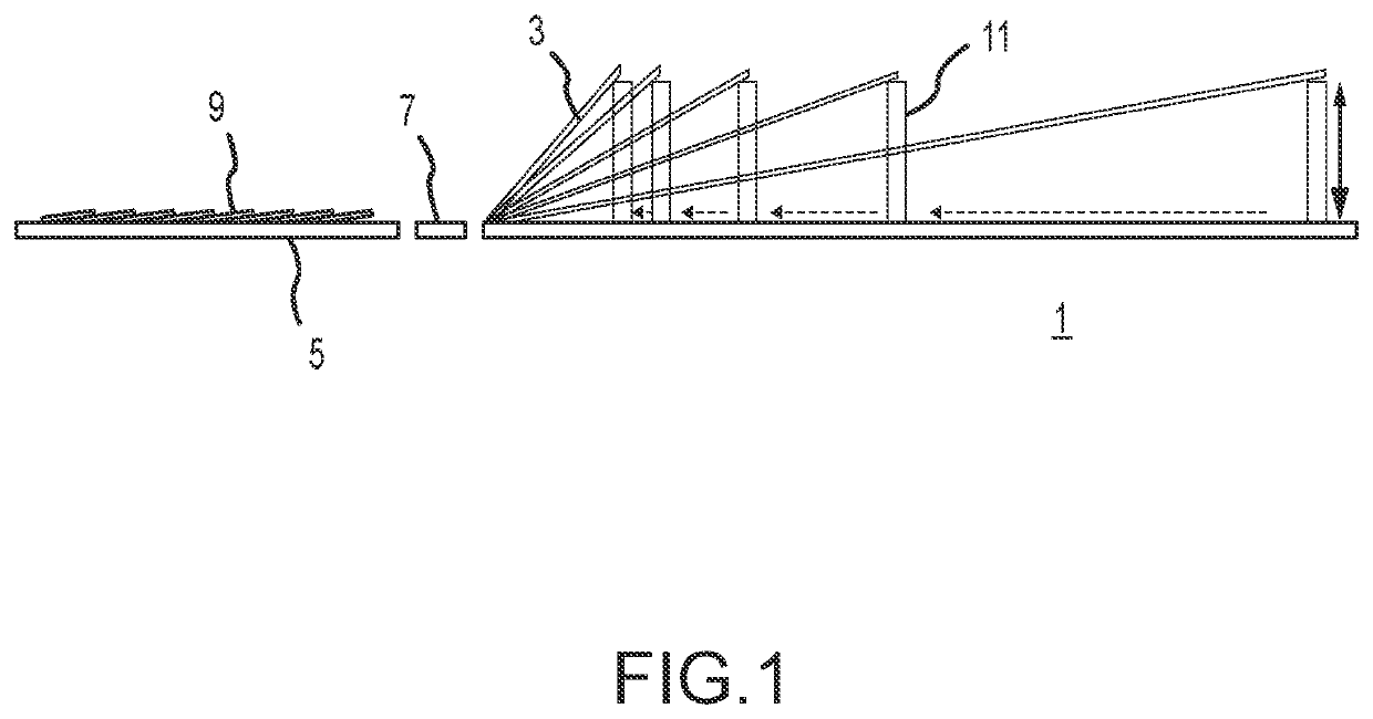
[0038]FIG. 1 is a side view of the rework device according to an exemplary embodiment of the present disclosure. As shown in FIG. 1, in the illustrated embodiment, the rework device 1 mainly includes a first supporting component 3, a second supporting component ...
PUM
 Abstract
Description
Claims
Application Information