
Lighting-emitting Diode Chip and Manufacturing Method, Display Device

a technology of light-emitting diodes and manufacturing methods, applied in the field of semiconductor devices, can solve the problems of low luminous efficiency, more area loss of light-emitting layers, and process difficulty, and may be an urgent problem to be solved

Pending Publication Date: 2022-07-07
CHONGQING KONKA PHOTOELECTRIC TECH RES INST CO LTD
View PDF0 Cites 0 Cited by
  • Summary
  • Abstract
  • Description
  • Claims
  • Application Information

AI Technical Summary

Benefits of technology

The patent describes a new method for making a light-emitting diode chip and a display device using it. By creating a containing groove in the first semiconductor layer and arranging a metal layer in it, the length of the first electrode is shortened and the position of the inclined groove is made shallower. This reduces the process difficulty and area loss of the light-emitting layer, leading to improved efficiency of the light-emitting diode. The display device composed of multiple light-emitting diode chips has higher luminous efficiency. Overall, this technology advancement simplifies the manufacturing process and increases the efficiency of light-emitting diodes.

Problems solved by technology

However, this arrangement means of the inclined groove is very difficult so that it needs to spend more process time, which may cause more area loss of the light-emitting layer and low luminous efficiency.
Therefore, reducing the area loss of the light-emitting layer and the process difficulty may be an urgent problem to be solved.

Method used

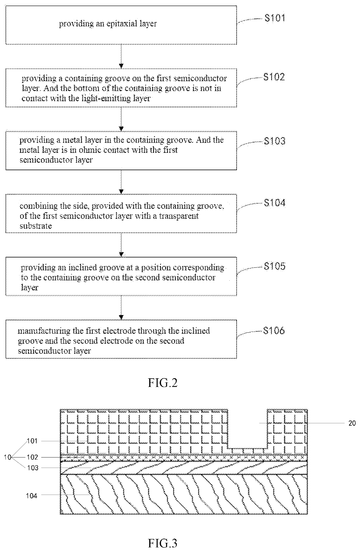
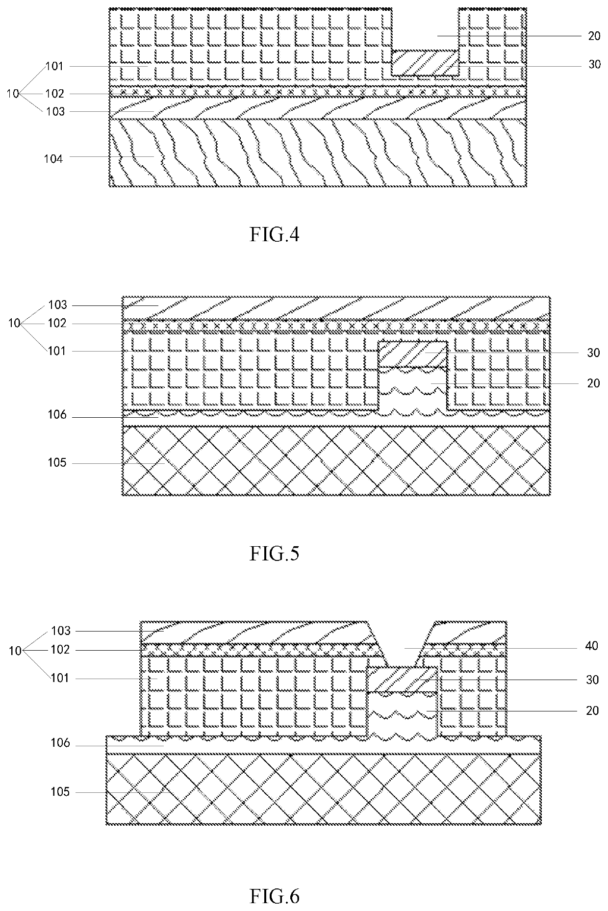

Image

  • Lighting-emitting Diode Chip and Manufacturing Method, Display Device
  • Lighting-emitting Diode Chip and Manufacturing Method, Display Device
  • Lighting-emitting Diode Chip and Manufacturing Method, Display Device

Examples


Embodiment Construction

[0043]To facilitate to understand of the disclosure, more comprehensive description of the disclosure will be applied according to the reference drawings. A preferred embodiment of the disclosure is given in the drawings. However, the disclosure may be implemented in many different forms and not be limited to the embodiments described herein. On the contrary, the purpose of providing these embodiments is to provide a more thorough and comprehensive understanding of the disclosure.

[0044]Unless defined specially, all technical and scientific terminology used herein have the same meaning as commonly understood by ordinary skilled in the field of the disclosure. The terminology in the specification of the disclosure is only used for describing particular embodiments but not intended to limiting the disclosure.

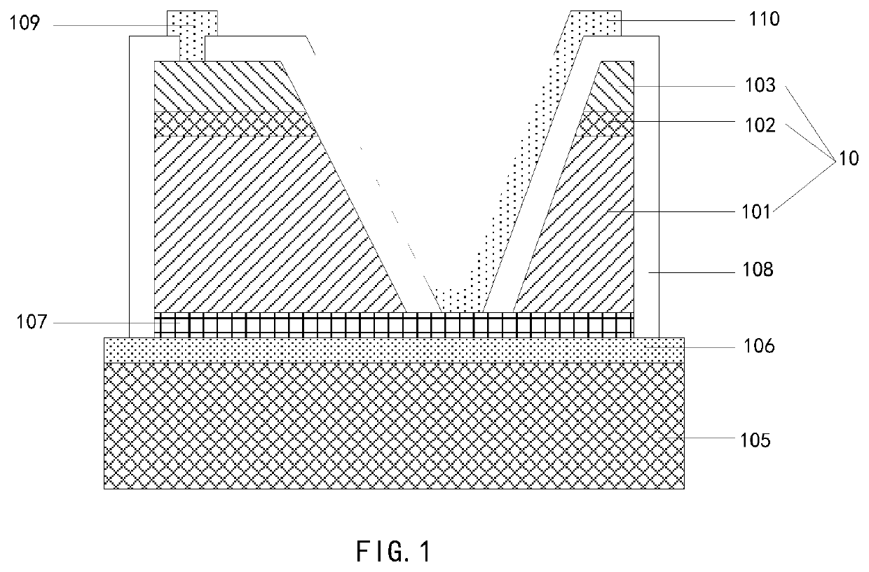
[0045]In some embodiments, referring to FIG. 1, the structure of a light-emitting diode generally includes a transparent substrate 105, an epitaxial layer 10, a transparent bonding...


PUM


Abstract

The disclosure relates to a light-emitting diode chip and a manufacturing method thereof, and a display device. The light emitting diode chip includes a transparent substrate, an epitaxial layer, a first electrode and a second electrode. The epitaxial layer includes a first semiconductor layer, a second semiconductor layer, and a light-emitting layer. A containing groove is formed in the first semiconductor layer, and a metal layer is arranged in the containing groove. The metal layer is in ohmic contact with the first semiconductor layer. The second semiconductor layer is provided with an inclined groove, and the transparent substrate is combined with the first semiconductor layer. The first electrode is arranged in the inclined groove, and the second electrode is arranged on the second semiconductor layer.

Description

CROSS REFERENCE TO RELATED APPLICATION[0001]The present application is a non-provisional application and is a continuation application of PCT / CN2021 / 083586 filed on Mar. 29, 2021, PCT / CN2021 / 083586 claiming the benefit of priority to a Chinese Patent Application number CN202011337564.6, filed on Nov. 25, 2020, the disclosure of the above application is hereby incorporated by reference in its entirety for all purposes.TECHNICAL FIELD[0002]The disclosure relates to the field of semiconductor devices, and in particular, relates to a light-emitting diode chip, its manufacturing method, and display devices that incorporate this light-emitting diode chip.BACKGROUND[0003]Light Emitting Diode (LED) is a new generation of display technology. Compared with liquid crystal display in similar technology, it has higher photoelectric efficiency, higher brightness, higher contrast and lower power, and can realize flexible display in combination with a flexible panel. Such that it can be widely appl...

Claims


Application Information

Patent Timeline
IPC IPC(8): H01L33/38H01L25/075H01L33/00H01L33/20
CPCH01L33/382H01L25/0753H01L2933/0016H01L33/20H01L33/005H01L33/36H01L33/0093
Inventor WANG, TAOSHEN, CHIA-HUIWU, KAI-YI
Owner CHONGQING KONKA PHOTOELECTRIC TECH RES INST CO LTD
Learn More