Three-stage tubular t-shaped degassing device with microbubble axial flow and spiral flow fields

a axial flow and spiral flow technology, applied in the direction of liquid degasification, separation process, borehole/well accessories, etc., can solve the problems of reducing separation performance, reducing separation efficiency, and relatively low separation efficiency

Pending Publication Date: 2022-07-14
QINGDAO TECHNOLOGICAL UNIVERSITY
View PDF0 Cites 0 Cited by
  • Summary
  • Abstract
  • Description
  • Claims
  • Application Information

AI Technical Summary

Problems solved by technology

Furthermore, the separation efficiency is relatively low, which cannot meet the current high requirement for oil-gas separation efficiency.
However, when the separator is applied to mist flow and slug flow with high gas-liquid ratio and hi

Method used


Image

  • Three-stage tubular t-shaped degassing device with microbubble axial flow and spiral flow fields
  • Three-stage tubular t-shaped degassing device with microbubble axial flow and spiral flow fields
  • Three-stage tubular t-shaped degassing device with microbubble axial flow and spiral flow fields

Examples


Embodiment Construction

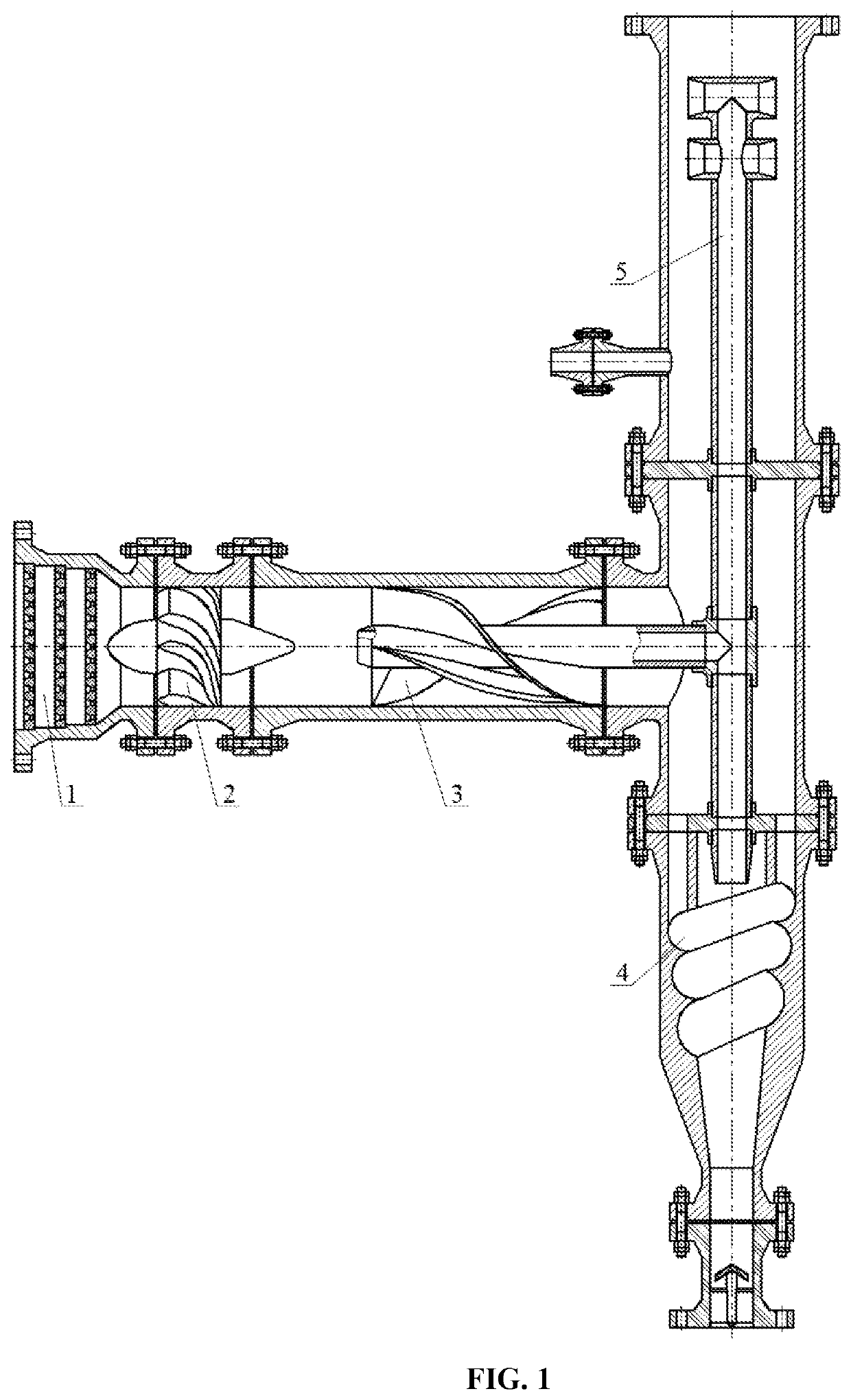
[0047]In FIG. 1, a three-stage tubular type T-shaped degassing device with microbubble axial flow and spiral flow fields includes a microbubble uniform mixer 1, a microbubble cyclone 2, a rotational axial flow degasser 3, a conical spiral flow degasser 4, and a jet reversing degasser 5, and adopts a quick degassing technology combining a microbubble uniform mixed rotational axial flow field and a spiral runner conical spiral flow field with layered jet collision reversing degassing to sequentially implement a horizontal type microbubble uniform mixed multiple strands rotational axial flow degassing operation, a vertical type spiral runner and single-strand conical spiral flow degassing operation, and a vertical type layered jet collision reversing degassing operation. A reversing buffer column pipe body of the jet reversing degasser 5 is connected to a gas transportation manifold by a flange plate, and the degassed reversing gas is pressurized and then transported to the outside. A ...


PUM

PropertyMeasurementUnit
Diameteraaaaaaaaaa

Abstract

A three-stage tubular T-shaped degassing device with microbubble axial flow and spiral flow fields is provided, which is applied to quick degassing of a gas-liquid two-phase flow. The three-stage tubular T-shaped degassing device adopts a quick degassing technology combining a microbubble uniform mixed rotational axial flow field and a spiral runner conical spiral flow field with layered jet collision reversing depth degassing. A microbubble uniform mixer is configured to adjust gas-liquid two-phase flow containing big bubbles into microbubble uniform mixed axial flow. A microbubble cyclone is configured to adjust the microbubble uniform mixed axial flow into multiple strands of rotational axial flows containing microbubbles. A rotational axial flow degasser implements the horizontal type microbubble uniform mixed multiple strands rotational axial flow degassing operation to remove most microbubbles to form axial flow gas and axial flow liquid.

Description

CROSS REFERENCE TO RELATED APPLICATION[0001]This patent application claims the benefit and priority of Chinese Patent Application No. 202110040894.7 entitled “Three-stage Tubular Type T-shaped Degassing Device with Microbubble Axial Flow and Spiral Flow Fields” filed on Jan. 13, 2021, the disclosure of which is incorporated by reference herein in its entirety as part of the present application.TECHNICAL FIELD[0002]The present disclosure relates to a tubular quick degassing device in the field of oil-gas field development and exploitation projects, in particular to a double-field three-stage tubular T-shaped degassing device combining a microbubble uniform mixed rotational axial flow field with a spiral runner conical spiral flow field, and an operation procedure of the same.BACKGROUND ART[0003]An efficient separation technology for gas-liquid two-phase flow has a very important practical significance for oil-gas field development and exploitation projects. The main reasons are that:...

Claims


Application Information

Patent Timeline
IPC IPC(8): B01D19/00
CPCB01D19/0047B01D19/0068B01D19/0057E21B43/34
Inventor LIU, XINFUHAO, ZHONGXIANCHEN, JIYU, CHAOYONGYU, GUANGHAIHAO, AIGANGWU, XIAOMINGWANG, JIANFENGXING, WENSHI, YONGJUNWANG, XIAOLEIZHANG, RUIQIANG
Owner QINGDAO TECHNOLOGICAL UNIVERSITY
Why Eureka
Try Eureka