
Cooling module for an electric motor vehicle, comprising a tangential-flow turbomachine

a technology of cooling module and electric motor vehicle, which is applied in the direction of machines/engines, mechanical equipment, transportation and packaging, etc., can solve the problems of limiting the exchange of heat with the heat transfer fluid, affecting the flow of air toward the exchanger, and affecting the uniformity of heat exchange across the entire surface of the tubes and fins

Pending Publication Date: 2022-07-21
VALEO SYST THERMIQUES
View PDF10 Cites 0 Cited by
  • Summary
  • Abstract
  • Description
  • Claims
  • Application Information

AI Technical Summary

Benefits of technology

The patent describes a cooling system for heat exchangers that uses turbomachines to create a flow of air through all of the heat exchangers with better efficiency. The arrangement of the two turbomachines reduces or prevents impact between air jets and ensures good ventilation and acoustic performance. The technical effects of this system are improved cooling efficiency and reduced noise levels.

Problems solved by technology

The exchange of heat is therefore not uniform across the entire surface of the tubes and of the fins.
Furthermore, when it is not necessary for the fan to be switched on (typically when the exchange of heat with non-accelerated ambient air is sufficient to cool the heat transfer fluid circulating in the exchanger), the blades partially obstruct the flow of the ambient air toward the tubes and the fins, thus impeding the circulation of air toward the exchanger and thus limiting the exchange of heat with the heat transfer fluid.
Such a fan is also relatively bulky, in particular because of the necessary dimensions of the blower wheel in order to obtain effective engine cooling, and this makes incorporating it into a motor vehicle a lengthy and difficult process.
This incorporation is all the more complicated in an electric vehicle, the front face of which leaves very little space in which to house the vehicle cooling elements.

Method used


Image

  • Cooling module for an electric motor vehicle, comprising a tangential-flow turbomachine
  • Cooling module for an electric motor vehicle, comprising a tangential-flow turbomachine
  • Cooling module for an electric motor vehicle, comprising a tangential-flow turbomachine

Examples


Embodiment Construction

[0027]In the remainder of the description, elements that are identical or perform identical functions bear the same reference sign. In the present description, for the sake of conciseness, these elements are not described in detail within each embodiment. Rather, only the differences between the variants are described in detail.

[0028]It will be noted that, in the preferred examples illustrated, each turbomachine operates by suction, that is, it draws in ambient air and conveys it so that it comes into contact with the various heat exchangers, as will be explained in detail. Alternatively however, each turbomachine operates by blowing, blowing the air toward the various heat exchangers.

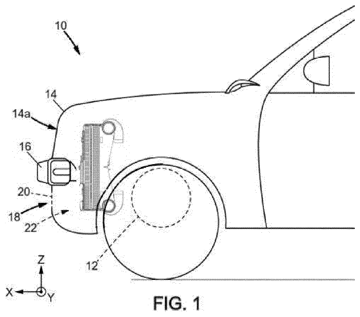
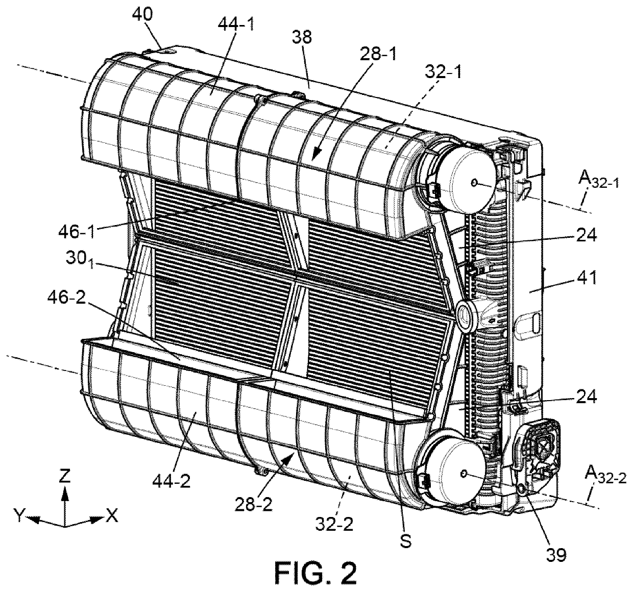
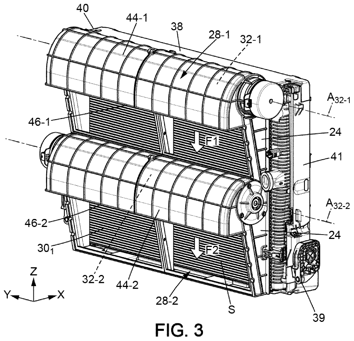
[0029]FIG. 1 schematically illustrates the front part of a motor vehicle 10 with an electric motor 12. The vehicle 10 comprises in particular a body 14 and a bumper 16 carried by a chassis (not shown) of the motor vehicle 10. The body 14 defines a cooling opening 18, that is, an opening through the bod...


PUM


Abstract

The invention relates to a cooling module (22) for a motor vehicle (10), comprising: ⋅—at least one heat exchanger (301-303) delimiting a surface, referred to as the working surface, ⋅—at least one first tangential-flow turbomachine (28-1) and a second tangential-flow turbomachine (28-2), each of said turbomachines (28-1, 28-2) being capable of creating an air flow in contact with said working surface, each of said turbomachines comprising a rotor rotating about an axis and a volute for housing the rotor, comprising an air guiding portion and an air outlet outside the turbomachine, said turbomachines (28-1, 28-2) being arranged such that the air outlet of the first turbomachine (28-1) is arranged opposite the guiding portion of the second turbomachine (28-2).

Description

TECHNICAL FIELD[0001]The invention relates to the field of motor vehicles, and more particularly to the field of air circulation for cooling the engine and its equipment.PRIOR ART[0002]Motor vehicles, whether of the combustion or electric type, have to discharge the heat generated by their operation, and are equipped with heat exchangers for this purpose. A motor vehicle heat exchanger generally comprises tubes in which a heat transfer fluid, in particular a liquid such as water, is intended to circulate, and heat exchange elements connected to these tubes, often designated by the term “fins” or “inserts”. The fins are used to increase the exchange surface between the tubes and the ambient air.[0003]However, in order to further increase the heat exchange between the heat transfer fluid and the ambient air, a ventilation device is often used in addition, to generate or increase a flow of air directed toward the tubes and the fins.[0004]As is known, such a ventilation device comprises...

Claims


Application Information

Patent Timeline
Patent Type & Authority Applications(United States)
IPC IPC(8): B60K11/08F01P11/10
CPCB60K11/085F01P5/06F01P11/10B60K11/06B60K11/08
Inventor AZZOUZ, KAMELGARNIER, SÉBASTIENLISSNER, MICHAELMAMMERI, AMRID
Owner VALEO SYST THERMIQUES
Learn More