Inlet cone for an aircraft turbine engine and associated aircraft turbine engine

a technology of turbine engines and inlet cones, which is applied in the direction of machines/engines, efficient propulsion technologies, and combustion-air/fuel-air treatment. it can solve the problems of disengagement from the tip, damage to the engine of the aircraft that ingests, and the fan blades it strikes

Active Publication Date: 2022-07-28
SN DETUDE & DE CONSTR DE MOTEURS DAVIATION S N E C M A
View PDF5 Cites 0 Cited by
  • Summary
  • Abstract
  • Description
  • Claims
  • Application Information

AI Technical Summary

Problems solved by technology

This tip is known to be a point in the turbine engine that promotes ice accretion, since its centering on the axis of rotation does not allow the application of significant centrifugal forces.
As a result, the ice forming on the inlet cone tip could grow to a large size before breaking off, with the risk, when it eventually disengages from the tip, of damaging the fan blades it strikes or the engine of the aircraft that ingests it.
The ice pack can also accumulate unevenly on the tip of the inlet cone, resulting in undesirable vibrations of the turbine engine.
However, this type of system is expensive in terms of mass and size, and above all particularly difficult to implement due to the rotating nature of the inlet cone that is equipped with it.
However, this way of detaching the ice layer, by embrittling it and allowing cracks to propagate along it, may be slower than expected in the case of in-flight operation of the turbine engine.
Indeed, the larger the size of the ice layer, the slower and more difficult it is to form cracks in this layer.
Such a solution is therefore not sufficient to quickly and completely detach the ice layer forming on the tip of the inlet cone.

Method used


Image

  • Inlet cone for an aircraft turbine engine and associated aircraft turbine engine
  • Inlet cone for an aircraft turbine engine and associated aircraft turbine engine
  • Inlet cone for an aircraft turbine engine and associated aircraft turbine engine

Examples


Embodiment Construction

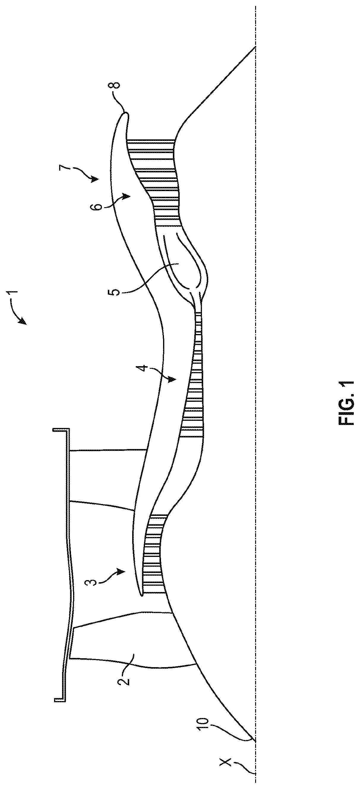
[0030]By convention in the present application, the terms “interior” and “exterior”, and “inner” and “outer” are defined radially with respect to a longitudinal axis X of the aircraft engine of the turbine engine. Thus, a cylinder extending along the axis X of the engine comprises an interior surface facing the axle of the engine and an exterior surface opposite its interior surface. “Axial” or “axially” means any direction parallel to the axis X and “transversely” or “transverse” means any direction perpendicular to the axis X. Similarly, the terms “upstream” and “downstream” are defined with respect to the direction of airflow in the turbine engine.

[0031]FIG. 1 shows a turbine engine 1 with dual flow. However, this is not limiting and the turbine engine may be of another type, such as for example a turboprop engine.

[0032]The turbine engine 1 extends along a longitudinal axis X and comprises from upstream to downstream, in the direction of the gas flow, a fan 2, one or more compres...


PUM

PropertyMeasurementUnit
angleaaaaaaaaaa
angleaaaaaaaaaa
angleaaaaaaaaaa

Abstract

The present invention thus proposes an inlet cone for an aircraft turbine engine, comprising a frustoconical body and a tip made from elastically deformable material fixed to an end of smaller diameter of said body, the tip comprising a top configured to be situated on an axis of rotation of the cone and a fastening base for attachment on said end of said body. Said base extends in a connecting plane P. Said connecting plane P is inclined relative to said axis of rotation. Said base has a generally circular or oval shape. According to the invention, said connecting plane P is inclined relative to a transverse plane T perpendicular to said axis of rotation.

Description

TECHNICAL FIELD OF THE INVENTION[0001]The field of the present invention is that of turbine engines, in particular that of gas turbine engines, for example and not restrictively a turbojet engine or an aircraft turboprop.[0002]The present invention relates more particularly to an air inlet cone for a turbine engine.TECHNICAL BACKGROUND[0003]The prior art comprises, in particular, the documents GB-A-1 557 856, FR-A1-2 943 726, FR-A1-3 027 878, FR-A1-2 943 725 and FR-A1-2 898 939.[0004]It is known from the prior art that turbine engines extend along a longitudinal axis and comprise, from upstream to downstream, in the direction of gas flow, a fan, one or more compressor stages (e.g., a low-pressure compressor and a high-pressure compressor), a combustion chamber, one or more turbine stages (e.g., a high-pressure turbine and a low-pressure turbine), and a gas exhaust nozzle.[0005]Conventionally, such turbine engines further comprise an upstream air inlet cone which is mounted on the fa...

Claims


Application Information

Patent Timeline
Patent Type & Authority Applications(United States)
IPC IPC(8): F01D25/02F01D5/02F02C7/047B64C11/14B64D15/16
CPCF01D25/02F01D5/02F02C7/047F05D2240/24B64D15/16F05D2220/323B64C11/14F02C7/04F05D2250/232F05D2250/314F05D2250/73F05D2300/431F01D5/025Y02T50/60
Inventor BATONNET, BAPTISTE RENE ROGERLOUIS, ALBAN FRANCOIS
Owner SN DETUDE & DE CONSTR DE MOTEURS DAVIATION S N E C M A
Why Eureka
Try Eureka