Eureka AIR delivers breakthrough ideas for toughest innovation challenges, trusted by R&D personnel around the world.

Output distribution method of power supply system

Pending Publication Date: 2022-07-28
HYOSUNG HEAVY IND CORP
View PDF0 Cites 0 Cited by
  • Summary
  • Abstract
  • Description
  • Claims
  • Application Information

AI Technical Summary

Benefits of technology

This patent is for a method for distributing power in a power supplying system that improves overall efficiency by taking into account the specific needs and circumstances of the site where the system is located. This results in increased lifespan for the power conditioning system used in the system.

Problems solved by technology

However, the existing smart grid system does not present an appropriate method of distributing energy in order to efficiently use supplied energy.
Such a PV system is operated in an area with high efficiency at the time of maximum output but is operated in an area with low efficiency in a low power generation state, resulting in loss of a power generation amount.
however, the lithium ion battery is less economical, but due to good output characteristics and high efficiency, the lithium ion battery has recently been widely applied.
However, in this case, without considering the plant characteristics and operating environment of a site in which a power supplying system is positioned, the power supplying system is operated in such a manner that outputs are simply distributed to individual PCSs according to the output efficiency of the individual PCSs or the efficiency according to a current charging amount, thereby resulting in a decrease in overall system efficiency.

Method used


Image

  • Output distribution method of power supply system
  • Output distribution method of power supply system
  • Output distribution method of power supply system

Examples


Embodiment Construction

[0037]Detailed embodiments for implementing the present invention will be described with reference to the accompanying drawings.

[0038]The present invention may be modified in various ways and implemented as various embodiments so that specific embodiments are illustrated in the drawings and will be described in detail below. However, it is to be understood that the present invention is not limited to the specific embodiments but includes all modifications, equivalents, and substitutions included in the spirit and the scope of the present invention.

[0039]Hereinafter, an output distribution method and apparatus of a power supplying system according to the present invention will be described in detail with reference to the accompanying drawings.

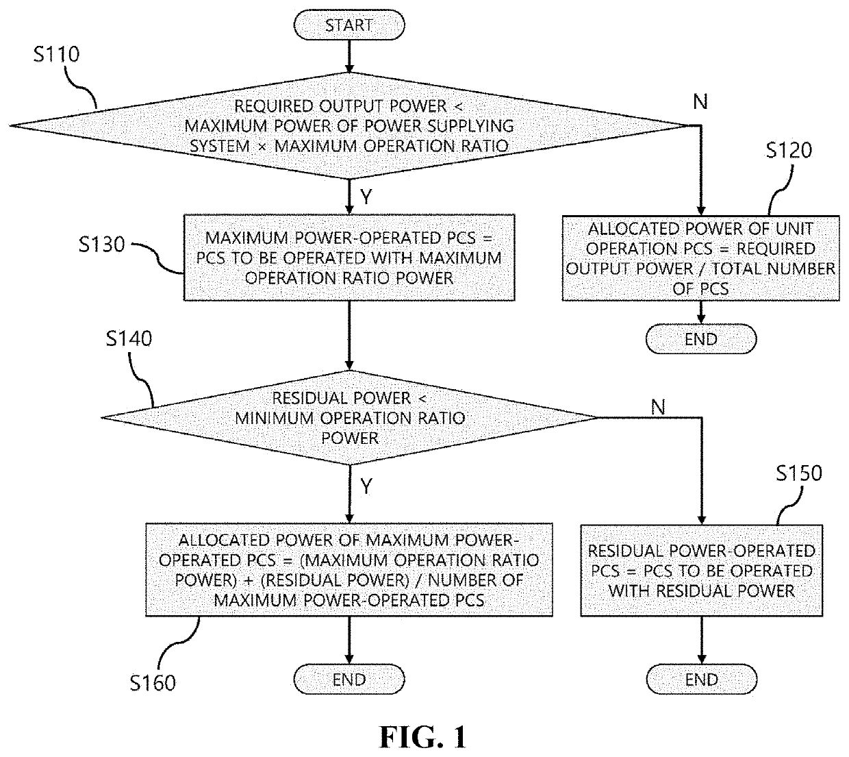
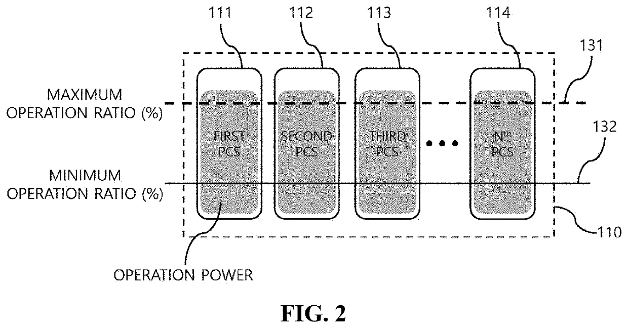
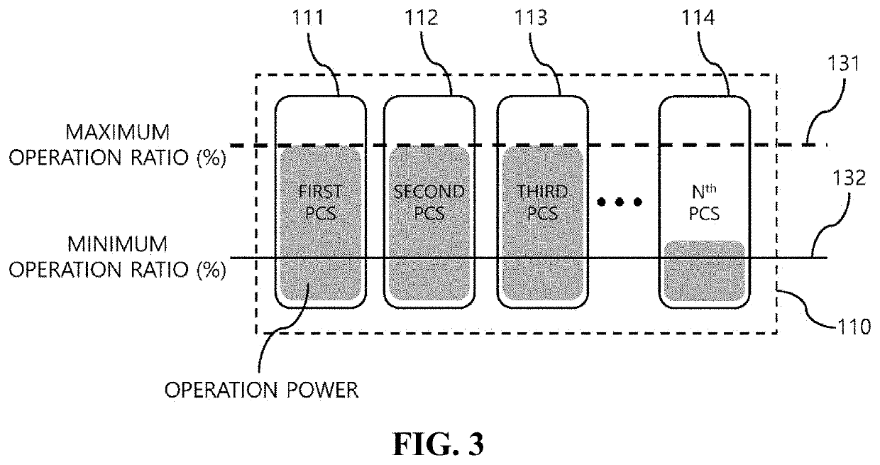
[0040]FIG. 1 is a flowchart illustrating an output distribution method of a power supplying system according to one embodiment of the present invention, and FIGS. 2 to 5 are detailed drawings and graphs for describing FIG. 1 in detail. In additi...


PUM


Abstract

An output distribution method of a power supply system includes: if a required output power of a power supply system exceeds a reference value, assigning the required output power equally to all PCSs; if the required output power does not exceed the reference value, assigning at least one maximum power driving PCS to be operated with a maximum driving ratio power, on the basis of a maximum driving ratio and a lowest driving ratio; if a remaining power unassigned during power assignment of the maximum power driving PCS exceeds a lowest driving ratio power, assigning a remaining power driving PCS for operation of the remaining power; and if the remaining power unassigned during the power assignment of the maximum power driving PCS does not exceed the lowest driving ratio power, equally dividing and reassigning the required output power to the maximum power driving PCS.

Description

TECHNICAL FIELD[0001]The present invention relates to a power distribution method of a power supplying system, and more particularly, to a method of distributing power at optimal efficiency in a power supplying system including a plurality of power conditioning systems (PCSs) or a plurality of power electronics building blocks (PEBBs; hereinafter, referred to as “PEBBs”). That is, the present invention relates to a method of controlling an operation of a plurality of PCSs or a plurality of PEBBs in a power supplying system according to an operating environment.BACKGROUND ART[0002]In order to construct a smart power grid through efficient power management of power facilities, industrial facilities, and private facilities, smart grid technology, in which information technology (IT) is applied to an existing power grid, is emerging.[0003]In a smart grid environment, a hybrid network, in which various devices are mixed and wired and wireless networks are combined, is constructed. For ex...

Claims


Application Information

Patent Timeline
IPC IPC(8): H02J3/14H02J3/46
CPCH02J3/144H02J2203/10H02J3/46Y02B70/3225Y04S20/222H02J3/38H02J2300/24
Inventor KIM, JEONG JOONGPARK, JONG HYUNG
Owner HYOSUNG HEAVY IND CORP
Why Eureka
Eureka Blog
Learn More