Apparatus for enclosing a chemical looping process

a technology of looping process and apparatus, which is applied in the direction of lighting and heating apparatus, apparatus for fluidised bed combustion, and combustion types, etc., can solve the problem of not being able to achieve adiabatic operation

Pending Publication Date: 2022-08-04
THE BABCOCK & WILCOX CO
View PDF3 Cites 2 Cited by
  • Summary
  • Abstract
  • Description
  • Claims
  • Application Information

AI Technical Summary

Benefits of technology

[0001]The present invention relates generally to an apparatus for housing a chemical looping process comprising of at least one fluidized-bed combustor reactor, at least one entrained riser, at least one p

Problems solved by technology

Current chemical looping system lose heat through the walls of

Method used


Image

  • Apparatus for enclosing a chemical looping process
  • Apparatus for enclosing a chemical looping process
  • Apparatus for enclosing a chemical looping process

Examples


Embodiment Construction

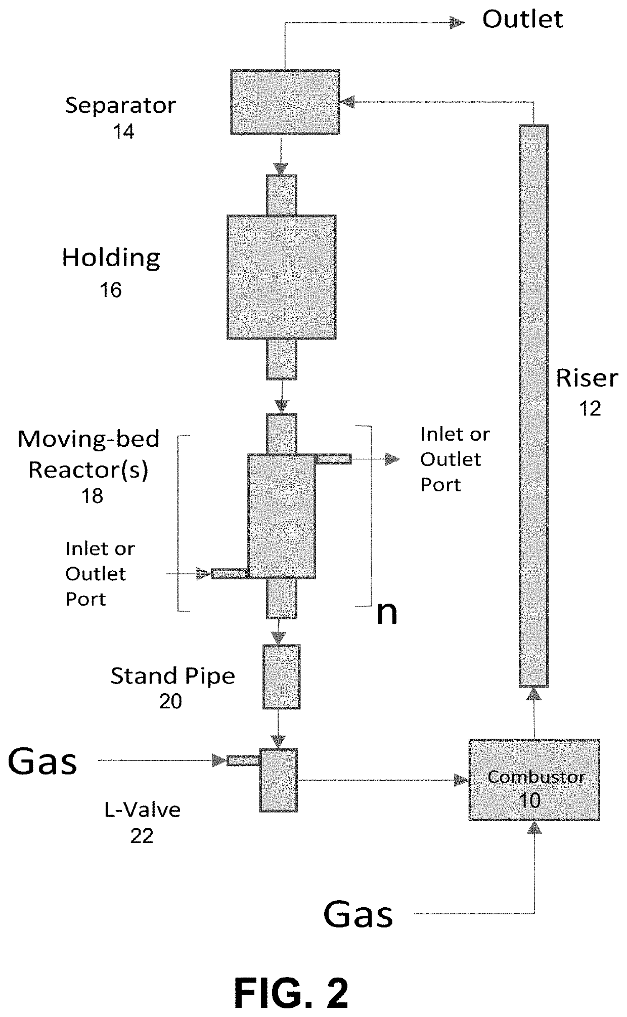
[0025]The present invention relates generally to an apparatus for housing a chemical looping process comprising of at least one fluidized-bed combustor reactor, at least one entrained riser, at least one particle separator, optionally at least one particle holding reactor, at least one moving-bed reactor, at least one standpipe, at least one L-valve system for solid flow control and interconnecting sections.

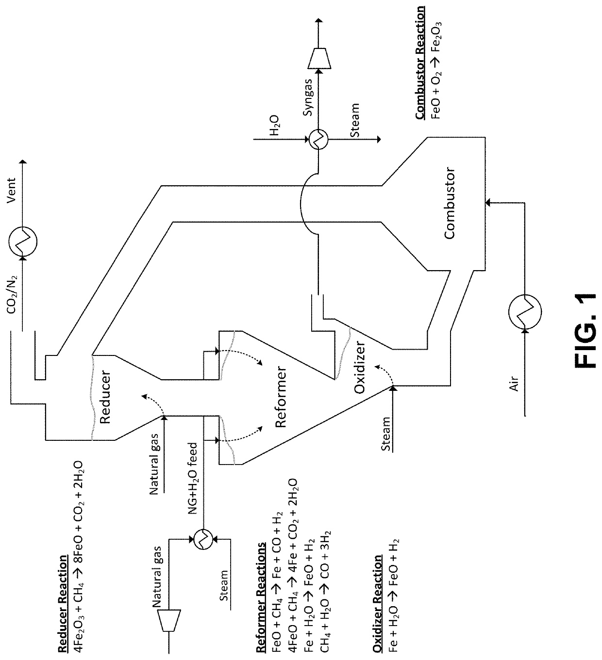
[0026]The present invention provides systems, apparatuses and methods for using chemical looping with a fuel source, in conjunction with steam reduction using a metal such as for example iron, to produce synthesis gas (CO+H2), hydrogen gas and / or steam for the generation of electric power. The fuel can comprise a solid, liquid, or gaseous, carbon-based fuel. Examples of carbon-based fuels useful in the practice of embodiments of the present invention include, but are not limited to, coal, coal char, petroleum coke, oil, oil shale, oil sands, biomass, methane-rich gases, fuel-rich...


PUM


Abstract

The present invention relates generally to an apparatus for housing a chemical looping process comprising of at least one fluidized-bed combustor reactor, at least one entrained riser, at least one particle separator, optionally at least one particle holding reactor, at least one moving-bed reactor, at least one standpipe, at least one L-valve system for solid flow control and interconnecting sections.

Description

FIELD AND BACKGROUND OF THE INVENTION1. Field of the Invention[0001]The present invention relates generally to an apparatus for housing a chemical looping process comprising of at least one fluidized-bed combustor reactor, at least one entrained riser, at least one particle separator, optionally at least one particle holding reactor, at least one moving-bed reactor, at least one standpipe, at least one L-valve system for solid flow control and interconnecting sections.2. Description of the Related Art[0002]Without being bound to any one definition, chemical-looping technologies are technologies that do not use “free” oxygen, but make use of one or more metallic oxygen carriers, or catalysts to transfer the oxidizing agent to a fuel for full or partial conversion. Such processes are usually carried out in a connected fluidized-bed system, with an air reactor, in which a reduced metal is being oxidized. The product of the air reactor is typically nitrogen with several percent of oxyge...

Claims


Application Information

Patent Timeline
IPC IPC(8): B01J8/24B01J8/18B01J19/28C01B3/36B01J8/00F23C10/30F23C99/00
CPCB01J8/24B01J8/1845B01J19/28C01B3/36B01J8/005B01J8/009F23C2900/99008F23C99/006B01J2208/00132C01B2203/025B01J2208/00477B01J2219/1923F23C10/30C01B3/44C01B3/10
Inventor HOUSLEY, DONALD C.CUNNINGHAM, ROBERT T.FLYNN, THOMAS J.VELAZQUEZ-VARGAS, LUIS G.BAO, JINHUAREMUS, JEREMY L.BENNETT, ALBERT J.
Owner THE BABCOCK & WILCOX CO
Why Eureka
Try Eureka