Battery control device, battery control method, operation management system, and operation management method

a technology of battery control device and operation management system, which is applied in the direction of battery/fuel cell control arrangement, secondary cell servicing/maintenance, instruments, etc., and can solve problems such as the decrease of the operation rate of vehicles

Pending Publication Date: 2022-08-04
TOYOTA JIDOSHA KK
View PDF0 Cites 0 Cited by
  • Summary
  • Abstract
  • Description
  • Claims
  • Application Information

AI Technical Summary

Problems solved by technology

Particularly, in commercial vehicles such as regular-route buses and taxis, a long charging period of time causes a decrease in operation rate of vehicles.

Method used


Image

  • Battery control device, battery control method, operation management system, and operation management method
  • Battery control device, battery control method, operation management system, and operation management method
  • Battery control device, battery control method, operation management system, and operation management method

Examples


Embodiment Construction

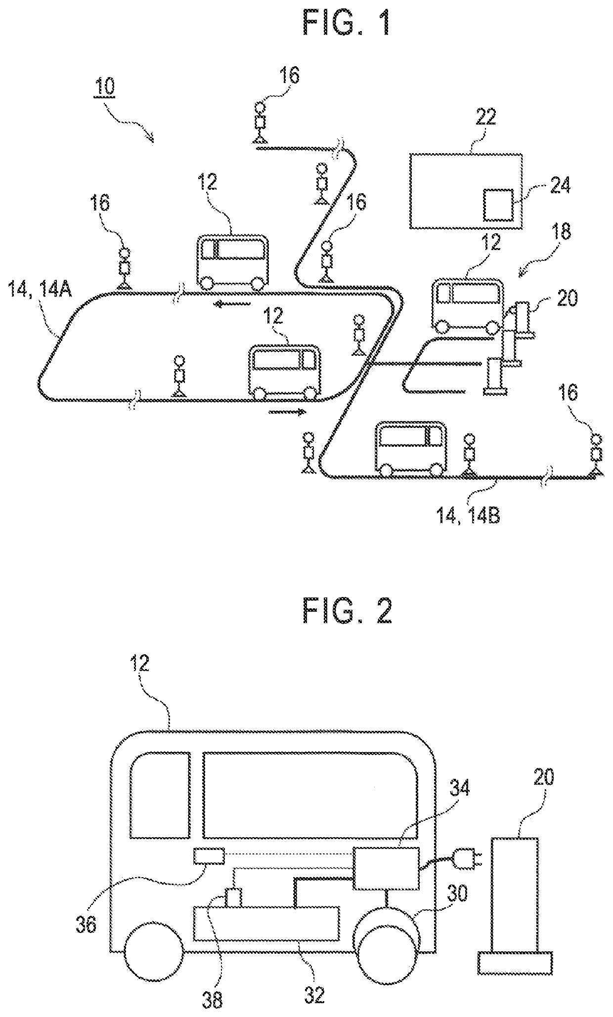
[0028]Hereinafter, an embodiment of the present disclosure will be described with reference to the accompanying drawings. FIG. 1 is a diagram schematically illustrating an operation system 10 of regular-route buses. A vehicle 12 which is a regular-route bus travels along a fixed route (regular route) 14 according to an operation plan, and a bus stop 16 is provided at a plurality of positions along the regular route 14. The operation system 10 includes two routes 14, that is, a circuit route 14A and a shuttle route 14B. The route may include only one of a circuit route and a shuttle route or may have more routes. The vehicle 12 circulates in one direction along the circuit route 14A or shuttles along the shuttle route 14B while stopping and starting at all bus stops 16 or at necessary bus stops 16. The vehicle 12 is a motor-driven vehicle that travels with electric power in a battery mounted therein. A charging station 18 is provided in the vicinity of the route 14 and the vehicle 12...


PUM

PropertyMeasurementUnit
temperatureaaaaaaaaaa
operation start timeaaaaaaaaaa
temperatureaaaaaaaaaa

Abstract

A battery control device includes: a charging/discharging control unit; an outside air temperature acquiring unit; and a state-of-charge upper limit setting unit setting a state-of-charge upper limit which is an upper limit of the management range of the state of charge when the acquired outside air temperature is lower than a predetermined air temperature to a low-temperature state-of-charge upper limit which is lower than the state-of-charge upper limit when the outside air temperature is higher than the predetermined air temperature. The battery control device further includes a state-of-charge lower limit setting unit setting a state-of-charge lower limit when the acquired outside air temperature is lower than the predetermined air temperature to a low-temperature state-of-charge lower limit which is lower than the state-of-charge lower limit when the outside air temperature is higher than the predetermined air temperature.

Description

CROSS-REFERENCE TO RELATED APPLICATION[0001]This application claims priority to Japanese Patent Application No. 2021-014185 filed on Feb. 1, 2021, incorporated herein by reference in its entirety.BACKGROUND1. Technical Field[0002]The present disclosure relates to battery control and operation management of a motor-driven vehicle.2. Description of Related Art[0003]A motor-driven vehicle travels by storing electric power in a battery mounted therein and driving a motor with the electric power. Characteristics of a battery change according to its temperature. A technique of changing charging / discharging control with a change in characteristics due to a change in temperature of a battery is known. Japanese Unexamined Patent Application Publication No. 2006-81300 (JP 2006-81300 A) discloses a technique of controlling a battery of a hybrid vehicle by changing an upper limit and a lower limit of an input / output voltage of the battery according to the temperature of the battery.SUMMARY[0004...

Claims


Application Information

Patent Timeline
Patent Type & Authority Applications(United States)
IPC IPC(8): H01M10/44H01M10/48B60L58/12G01R31/382B60W10/26
CPCH01M10/443H01M10/486B60L2240/545G01R31/382B60W10/26B60L58/12B60L58/13B60L58/24B60L53/665B60L53/62B60L3/0046H01M10/425H01M2010/4271H01M2010/4278B60L58/25B60L2240/662B60L2260/56B60L2260/52B60L2260/54
Inventor KONISHI, TOSHIYUKI
Owner TOYOTA JIDOSHA KK
Why Eureka
Try Eureka