WEB BROWSER BASED DEVELOPMENT PLATFORM FOR CREATING IoT WEB PAGES

a web browser and development platform technology, applied in the direction of electrical programme control, program control, instruments, etc., can solve the problems of large amount of code, high cost of devices, and high hardware design and software design costs

Pending Publication Date: 2022-08-11
CHOO PENG
View PDF1 Cites 0 Cited by
  • Summary
  • Abstract
  • Description
  • Claims
  • Application Information

AI Technical Summary

Benefits of technology

[0007]The development web page makes use of touch-screen and graphical interface devices that the user is likely to already own. It thereby simplifies and speeds the programming development cycle compared to previous systems. This way the programming code is available to the control device allowing it to be fully accessible and usable for programming on any device able to display and run web pages. It thereby eliminates the need for any specific hardware, operating system or server for the user to develop a custom web page interface and display incorporating control device outputs and inputs.
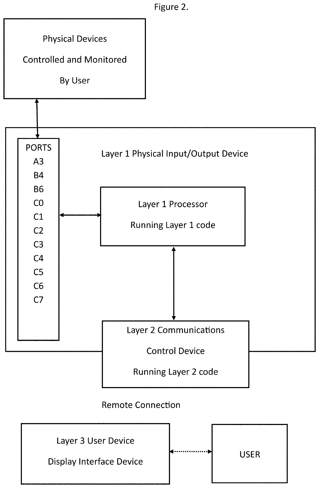
[0009]Since the physical input / output control device code only needs to perform interface functions on this system then the RAM and CPU speed needed are low thus allowing for a lower cost device to be used. Another advantage over previous systems is that the communications controller contains most of the code in the system and hence creates a flexible interface between many types of user interface devices and input / output control devices.

Problems solved by technology

These systems typically involve expensive and complex hardware designs and inefficient software designs.
Due to such inefficiencies, these systems contain large amounts of code that require large amounts of RAM and high CPU speeds to support any reasonably robust networking infrastructure.
This makes the devices expensive, difficult to program and unsuitable for certain applications.
These many steps have made IoT system development difficult and time consuming.

Method used


Image

  • WEB BROWSER BASED DEVELOPMENT PLATFORM FOR CREATING IoT WEB PAGES
  • WEB BROWSER BASED DEVELOPMENT PLATFORM FOR CREATING IoT WEB PAGES
  • WEB BROWSER BASED DEVELOPMENT PLATFORM FOR CREATING IoT WEB PAGES

Examples


example 1

System

[0044]This example will describe the steps to develop a sound alarm using this development platform.

[0045]The user will control a buzzer connected to port C4 of the microcontroller and detect the state of the button connected to port A3 of the microcontroller.

[0046]After connecting the devices to the microcontroller, the user interacts with the development platform as shown on FIG. 5. The user configures port A3 by selecting DIGITAL_IN and typing the name “Button”. The development platform then immediately reads the state of the microcontroller and displays 0 in STATUS to indicate a digital low signal on the microcontroller port input. Similarly, the user configures port C4 to DIGITAL_OUT and names it “Buzzer”. The development platform then immediately configures the C4 microcontroller port as a digital output and indicates that it is in a low state by displaying a red OFF button on the development platform interface. At this stage the user can test the buzzer connection by pr...

example 2

Automatically Turns on when Light Level is Low and Off when Light Level is not Low

[0061]FIG. 18; the user configures port C5 as “Digital_Out” and names it “Lightbulb”. The user configures port C7 as “Analog_In” and names it “Lightsensor”. The STATUS of port C7 then immediately displays a reading of the microcontroller port C7 as a number between 0 to 255 and is updated in real time on the development platform display in response to the microcontroller port C7 input voltage.

[0062]FIG. 19; the user then follows steps similar to example 1 to enter the JavaScript and JavaScript Loop code but this time using the AnalogIn function to read the 0 to 255 reading from microcontroller port C7 to turn on the port C5 light when the reading is below 100 and turn off port C5 light when the reading if not below 100.

example 3

Creates a New IoT Web Page that Includes User Created Buttons to Control an LED and a Buzzer on the Microcontroller

[0063]FIG. 20; similar to previous examples, the user configures and names the buzzer and LED ports.

[0064]FIG. 21; the user types HTML code into the HTML box on the development platform and includes the “turnOn” and“turnOff” functions directly into the HTML button code by direct reference to the buzzer and LED names. Note that only 2 lines of code are needed to create an ON button and an OFF button.

[0065]By pressing the “Run Code” button on the development platform, the user can preview and test the functionality of the new web page and the created buttons in the section of the development platform page that is in a separate box below all the other elements of the development platform.

[0066]The user can then send the developed new web page to the communications controller in the development system, by pressing the “Send” button that in near the top of the development pa...


PUM


Abstract

An internet of things IoT web page development platform for remote microcontroller device monitoring, control and display consisting of three layers. Layer one being the physical interface control for device input and output ports. Layer two being a communications controller that controls the layer one device and contains the user development environment and user developed web page. Layer three being the user's browser that displays and processes the web pages. The development platform is able to configure, control and sense ports directly from a web page. User's of the development platform can create a new IoT web page that includes systems outside the development platform such as systems on the user's device or resources on the communications network as part of the user developed web page.

Description

TECHNICAL FIELD[0001]This invention relates to improvements in systems for creating web pages that link to control devices via remote connections.BACKGROUND TO THE INVENTION[0002]Control devices (also called embedded devices, embedded controllers, embedded systems or microcontrollers) generally are devices whose primary purpose is to perform an independent action such as encoding video, controlling robots, routing internet traffic, and so on. Such devices run autonomously without user intervention, but there needs to be a way to program code into these devices.[0003]The current generation of control devices with remote connections use standard off-the-shelf components such as operating systems, file systems and web servers in order to provide the networking and application tasks. These systems typically involve expensive and complex hardware designs and inefficient software designs. Due to such inefficiencies, these systems contain large amounts of code that require large amounts of...

Claims


Application Information

Patent Timeline
Patent Type & Authority Applications(United States)
IPC IPC(8): G06F8/34
CPCG06F8/34H04L67/02G06F9/30003G06F9/22G06F9/445G05B19/0423G05B19/05G05B2219/20G05B2219/21012G05B2219/34444G05B19/0426G06F8/20
Inventor CHOO, PENG
Owner CHOO PENG
Why Eureka
Try Eureka