
Antenna structure and mobile device including the same

Active Publication Date: 2022-08-11
WISTRON NEWEB
View PDF1 Cites 0 Cited by
  • Summary
  • Abstract
  • Description
  • Claims
  • Application Information

AI Technical Summary

Benefits of technology

The present patent provides an improved design for an antenna structure that resonates the required frequency band for WI-FI 6E communication. It increases the coupling between the antenna and the feeding point, while reducing the required space for the antenna and without the need for additional changes in the mechanism. The number of antennas can be reduced, and molding costs can also be reduced. Additionally, the antenna structure achieves improved overall performance by adjusting the gap between the second grounded metal radiator and the feeding portion and the size of the second grounded metal radiator in the first direction.

Problems solved by technology

In this case, changing the appearance structure will cause the product to be redesigned, which is not cost-effective.

Method used


Image

  • Antenna structure and mobile device including the same
  • Antenna structure and mobile device including the same
  • Antenna structure and mobile device including the same

Examples


first embodiment

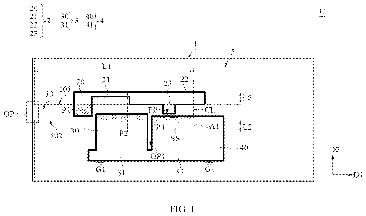
[0029]Referring to FIG. 1, FIG. 1 is a top schematic view of the antenna structure in the first embodiment of the present disclosure. The first embodiment provides a mobile device including a metal back cover 1 and an antenna structure U. The antenna structure U includes a feeding metal radiator 2, a first grounded metal radiator 3, a second grounded metal radiator 4, and a substrate 5. The metal back cover 1, feeding metal radiator 2, the first grounded metal radiator 3, and the second grounded metal radiator 4 may be made of metal materials, such as copper, silver, aluminum, iron, or alloys thereof.

[0030]The metal back cover 1 may be used in a metal casing of the mobile device. In some embodiments, the metal back cover 1 may be a metal upper case of a laptop or a metal back cover of a tablet but not limited thereto. The metal back cover 1 has an open slot 10. The open slot 10 has an open end OP and closed end CL which are arranged along a first direction D1. The open slot 10 has a...

second embodiment

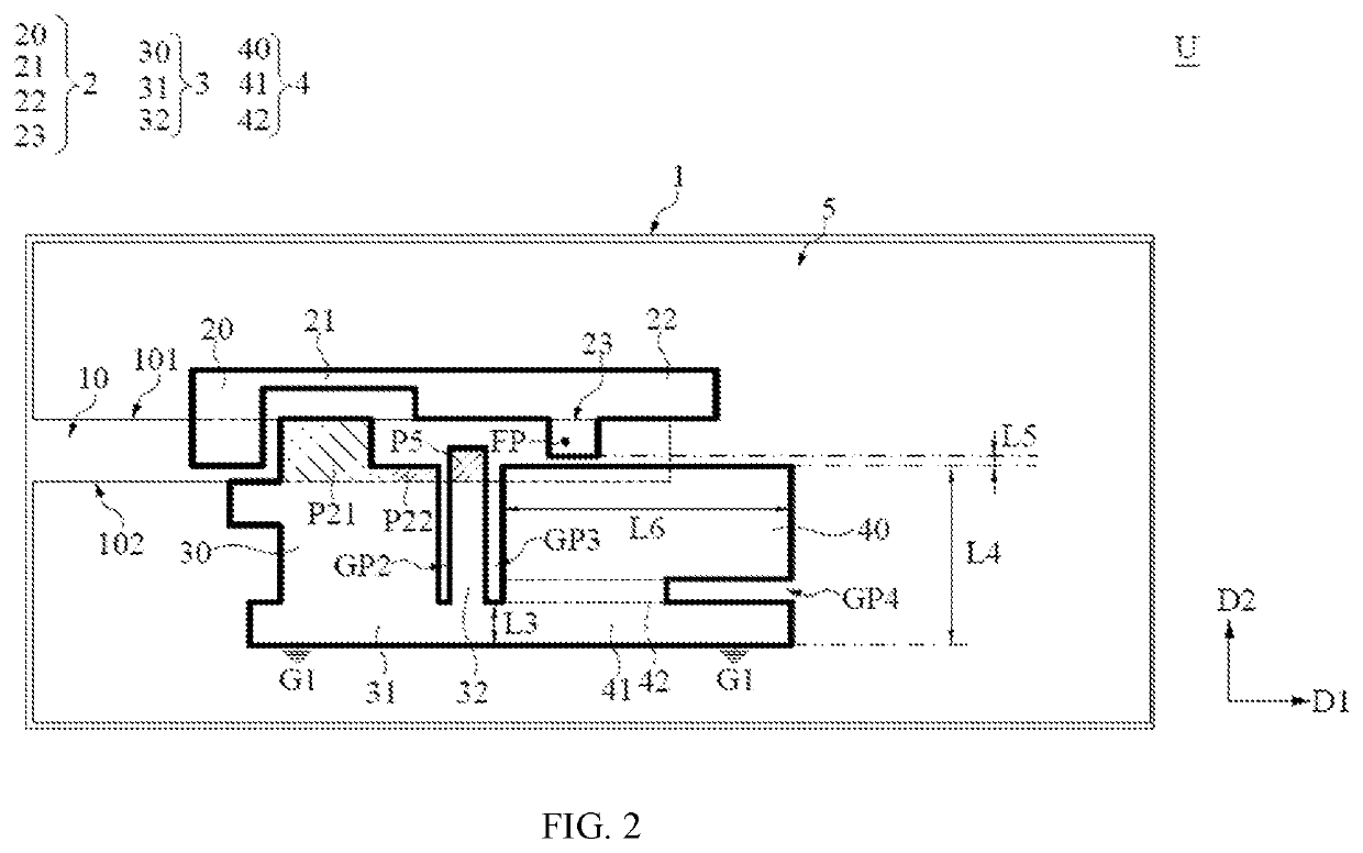
[0041]Referring to FIG. 2, FIG. 2 is a top schematic view of the antenna structure in the second embodiment of the present disclosure. The difference between the second embodiment and the first embodiment is that on the premise of preserving the gap between the first extension portion 30 and the second extension portion 40, the overall performance of the antenna structure U can be further improved by adjusting the structures of the first grounded metal radiator 3 and the second grounded metal radiator 4 provided by the second embodiment. In addition, the other structural features shown in the second embodiment are similar to the description of the foregoing embodiment, and would not be repeated here. In addition, for the clarity of the figures, some labels are omitted.

[0042]In the second embodiment, the first grounded metal radiator 3 further includes a third extension portion 32 positioned between the first extension portion 30 and the second extension portion 40. The third extensi...


PUM


Abstract

An antenna structure and a mobile device including the same are provided. The mobile includes a metal back cover and an antenna structure. The metal back cover has an open slot. The antenna structure includes a feeding metal radiator, a first grounded metal radiator, a second grounded metal radiator, and a substrate. The feeding metal radiator includes a first radiating portion, a first connecting portion, a second radiating portion and a feeding portion. The first radiating portion extends along a second direction from one side of the opening slot. The second radiating portion is coupled with the first radiating portion through the first connecting portion. The feeding portion is connected to the second radiating portion and extends along the second direction from one side of the open slot.

Description

CROSS-REFERENCE TO RELATED PATENT APPLICATION[0001]This application claims the benefit of priority to Taiwan Patent Application No. 110104403, filed on Feb. 5, 2021. The entire content of the above identified application is incorporated herein by reference.[0002]Some references, which may include patents, patent applications and various publications, may be cited and discussed in the description of this disclosure. The citation and / or discussion of such references is provided merely to clarify the description of the present disclosure and is not an admission that any such reference is “prior art” to the disclosure described herein. All references cited and discussed in this specification are incorporated herein by reference in their entireties and to the same extent as if each reference was individually incorporated by reference.FIELD OF THE DISCLOSURE[0003]The present disclosure relates to an antenna structure, and more particularly to an antenna structure suited for an open slot s...

Claims


Application Information

Patent Timeline
IPC IPC(8): H01Q13/10H01Q5/307H01Q1/48H01Q1/24
CPCH01Q13/10H01Q1/24H01Q1/48H01Q5/307H01Q5/371H01Q9/26H01Q21/293H01Q1/2258H01Q3/2605
Inventor TAI, CHIH-FENGLAI, KUAN-HSUNWANG, KUEI-CHENG
Owner WISTRON NEWEB
Learn More