Charging control method for electric moving body, and electric moving body
a charging control and electric moving body technology, applied in the control arrangement of battery/fuel cell, charging stations, transportation and packaging, etc., can solve the problems of user increasing the charging amount, power running out, and insufficient distribution remaining capacity
- Summary
- Abstract
- Description
- Claims
- Application Information
AI Technical Summary
Benefits of technology
Problems solved by technology
Method used
Image
Examples
first modification
[First Modification]
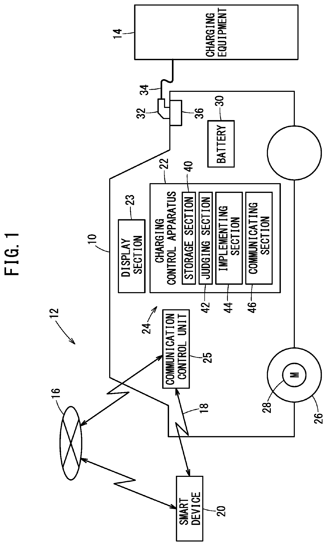
[0119]FIG. 8 is a system diagram showing a configurational example of a system 12A in which a portion of a charging control apparatus 22A is implemented in a management server 82 on the Internet, through the communication network 16.
[0120]The implementing section 44 is implemented in an electric vehicle 10A as a remaining portion of the charging control apparatus 22A. On the other hand, a storage section 40A, a judging section 42A, and a notifying section 46A, excluding the implementing section 44, are implemented as the charging control apparatus 22A of the management server 82.
[0121]In the system 12A of FIG. 8, the electric vehicle 10A includes the communication control unit 25, and the communication control unit 25 transmits and receives data to and from the management server 82 wirelessly via the communication network 16.
[0122]The management server 82 gathers various types of vehicle information (including information concerning each piece of charging equipme...
second modification
[Second Modification]
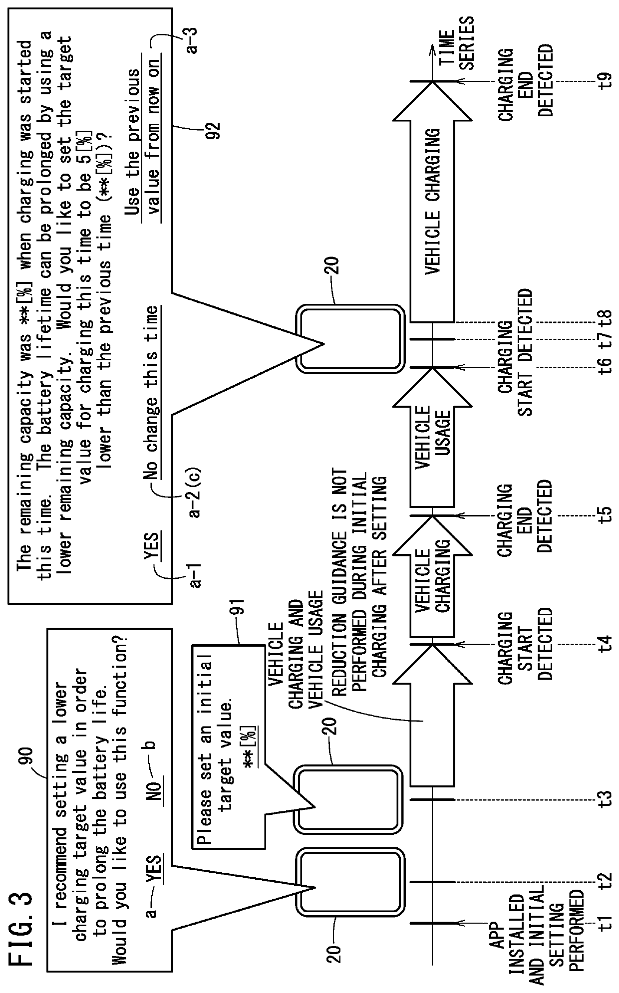
[0133]A function utilization recommending operation of the notification system (function activation recommending of the notification system) that provides notification recommending lowering of the target SOC is described while referencing FIG. 9.
[0134]The process according to the flow charts of FIGS. 4 and 5 is implemented at step S10 when a subsequent charging is started after the detection of the end of a charging.
[0135]The function utilization recommending operation is implemented in a case where usage of the function is continually stopped {a case where step S3 is affirmative (step S3: YES) a prescribed number of times} and the SOC at the charging start timing stays at high values each time.
[0136]Alternatively, the function utilization recommending operation is implemented in a case where the target SOC is continually fixed at a high position {a case where the continuing target SOC at step S16 (FIG. 5) is a high value} and the SOC at the charging start timin...
third modification
[Third Modification]
[0141]The target SOC setting process and target SOC reducing process corresponding to the deterioration influence characteristic 104, which is a battery characteristic of the battery 30, are described while referencing FIG. 10.
[0142]There is a minimal point 106 of deterioration influence in the deterioration influence characteristic 104. This minimal point is a point at which the deterioration influence switches from a decreasing trend to an increasing trend relative to an increase of the SOC.
[0143]With such a deterioration influence characteristic 104, when the target SOC is set to be less than or equal to the minimal point 106, there is a possibility that use by the user tending toward promoting deterioration will be induced over most of the range.
[0144]Therefore, in an electric vehicle 10 or 10A in which a battery 30 having such a deterioration influence characteristic 104 is loaded, the target SOC setting range is set to be from the minimal point 106 to 100[%...
PUM
 Abstract
Description
Claims
Application Information
 - R&D
- Intellectual Property
- Life Sciences
- Materials
- Tech Scout
- Unparalleled Data Quality
- Higher Quality Content
- 60% Fewer Hallucinations
Browse by: Latest US Patents, China's latest patents, Technical Efficacy Thesaurus, Application Domain, Technology Topic, Popular Technical Reports.
© 2025 PatSnap. All rights reserved.Legal|Privacy policy|Modern Slavery Act Transparency Statement|Sitemap|About US| Contact US: help@patsnap.com


