
Rechargeable battery

a rechargeable battery technology, applied in the field of batteries, can solve the problems of over-discharging the battery, increasing damage irreversibly the battery performance, so as to reduce the risk of internal short circuits, increase the lifetime, and ensure the effect of mechanical stability and/or strength

Inactive Publication Date: 2020-06-04
WYON
View PDF0 Cites 0 Cited by
  • Summary
  • Abstract
  • Description
  • Claims
  • Application Information

AI Technical Summary

Benefits of technology

The objective of this patent is to create a battery that can withstand being over-discharged without becoming less safe or performing poorly in the future. Specifically, the goal is to create a battery that can be deeply discharged down to zero Volt without causing safety risks or affecting the future performance of the battery.

Problems solved by technology

For fields of use in which a lithium ion battery is difficult to replace or remains inactive for a long period of time, one of the main safety issues is caused by the risk of over-discharging the battery, i.e. discharging of the battery below the lower voltage limit of 3 V. If a battery is discharged below said voltage limit of 3 V, the potential of the negative electrode rapidly increases above the copper dissolution limit.
This causes corrosion of copper if used as current collector in the negative electrode, which increases the risk of internal short circuits and damages irreversibly the battery performance.
Despite such protection circuits, over-discharge can still occur, in particular if a battery remains inactive and is not recharged for extended periods of time.
Therefore, other protection strategies to avoid copper dissolution at the negative electrode are of importance, particularly in those application fields such medical devices, aerospace and military devices, in which battery replacement or maintenance can be difficult or expensive.
The main disadvantage of such an approach is the increased operating potential of the negative electrode of around 1.5 V in contrast to the approximately 0.1 V of the carbonaceous active material, which in turn limits the energy density of the battery.
U.S. Pat. No. 8,535,831 B2 (Quallion LLC, 2009) suggests the use of stainless steel, nickel, titanium or other electrochemically stable metal current collectors as a replacement of copper negative current collectors to allow for discharge of the battery down to 0 V. Disadvantages of this approach are the increased weight and / or cost of the suggested battery compared to the conventional battery with copper negative electrode current collector.
The three previously mentioned inventions have the disadvantage of diminished volumetric capacity of the battery, as the auxiliary material having a smaller capacity occupies space potentially available for conventional, higher capacity materials.

Method used


Image

  • Rechargeable battery
  • Rechargeable battery

Examples


Embodiment Construction

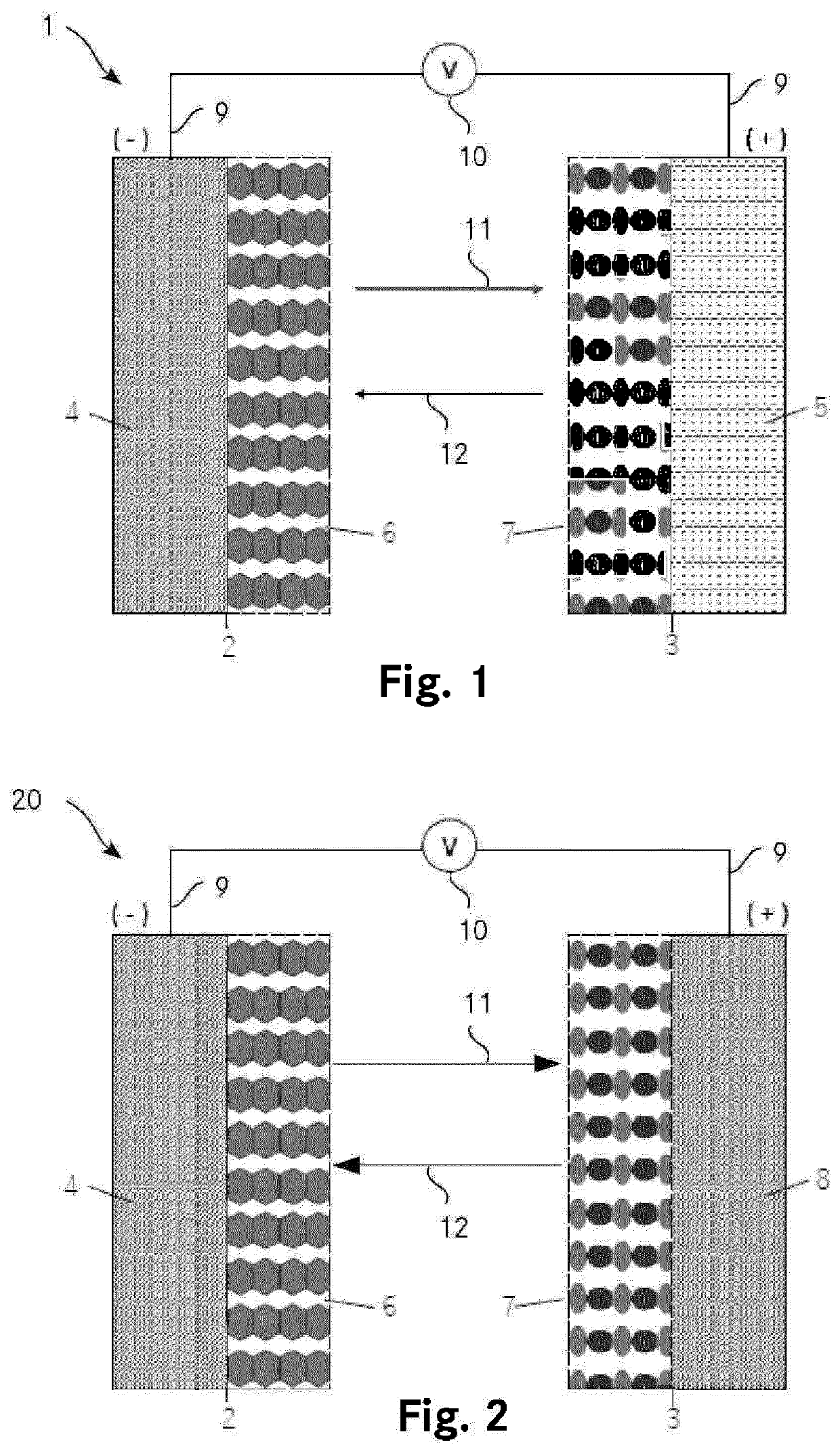
[0066]FIG. 1 shows an embodiment of a battery 1 comprising a lithium ion rechargeable battery cell. Battery 1 comprises a negative electrode 2. The negative electrode 2 comprises a negative current collector 4 made of an electrically conductive non-metallic structural material. The negative electrode 2 further comprises a negative active material 6, for example carbonaceous material. The negative current collector 4 and the negative active material 6 are electrically connected. The negative current collector 4 is further connected to a contacting fixture 9, which is finally connected to a load or charger 10. Battery 1 further comprises a positive electrode 3. The positive electrode 3 comprises a metallic positive current collector 5. For example, the metallic positive current collector 5 is made of aluminium. The positive electrode 3 further comprises a positive active material 7, as for example LiCoO2 or LiFePO4. The battery 1 comprises also a lithium electrolyte (not shown) which ...


PUM

PropertyMeasurementUnit
volumeaaaaaaaaaa
voltageaaaaaaaaaa
electrical conductivityaaaaaaaaaa

Abstract

A battery, in particular a rechargeable battery, with improved deep discharge stability is provided. The battery comprises at least one positive electrode with a positive current collector and at least one negative electrode with a negative current collector. The negative current collector is made of an electrically conductive non-metallic structural material, in particular structural carbon. Preferably, the battery is a lithium or lithium ion battery.

Description

TECHNICAL FIELD[0001]The invention relates to a battery, in particular to a rechargeable battery. The invention also relates to the use of a battery and to a method for manufacturing the battery.BACKGROUND ART[0002]Rechargeable lithium ion batteries are one of the preferred electrochemical energy storage devices for portable application, due to higher energy density and longer cycle life compared to other systems.[0003]Known rechargeable lithium ion batteries comprise a positive electrode having an active material as for example LiCoO2 supported on a metallic current collector as for example aluminium, and a negative electrode having an active material as for example carbonaceous material supported on a metallic current collector as for example copper. The two electrodes are spaced by a separator. An electrolyte is present to promote ionic conductivity between the two electrodes. Current collectors are used to collect the electric current from the electrodes and conduct it to the ou...

Claims


Application Information

Patent Timeline
Patent Type & Authority Applications(United States)
IPC IPC(8): H01M4/66H01M4/1393H01M10/0525H01M4/133H01M50/54
CPCH01M4/663H01M4/1393H01M10/0525H01M4/133H01M4/664H01M4/665H01M4/668H01M10/052Y02E60/10H01M50/54
Inventor SPREAFICO, CLELIA
Owner WYON
Learn More