Air cathode battery using zinc slurry anode with carbon additive

a technology of air cathode and carbon additive, which is applied in the field of electrochemical cells, can solve the problems of low zinc concentration, low efficiency, and inability to change the energy and capacity of flow-through zinc particle anodes, and achieves low cost, low viscosity, and improved viscosity.

Active Publication Date: 2017-03-28
SHARP KK
View PDF5 Cites 0 Cited by
  • Summary
  • Abstract
  • Description
  • Claims
  • Application Information

AI Technical Summary

Benefits of technology

[0009]Disclosed herein is a zinc-air battery with a scalable capacity enabled by coupling an air cathode with a low cost, zinc slurry anode. The slurry anode allows for a mechanical recharge of the zinc air battery. The zinc-air battery uses an anode in the form of highly concentrated zinc slurry with a sufficiently low viscosity that does not solidify after discharge. After being discharged, spent slurry can be replaced by fresh slurry pumped from a connected reservoir, so that mechanical charging is realized. The slurry anode includes zinc particles, alkaline solution, complexing agent, and carbon additives. Some unique aspects of the battery include the use of additives (e.g. graphite or carbon fiber) and complexing agents to improve viscosity, a mechanism to move slurry through the system to replace spent slurry with fresh slurry (mechanical charge), and a mechanism to maintain adequate water content in the slurry, so as to prevent the slurry from drying out, so the chemical reaction can proceed to completion. In this type of zinc-air battery, the zinc slurry is capable of a deep discharge (80% or greater) and high energy density. Since the slurry does not require continuous pumping, the battery efficiency is improved.

Problems solved by technology

Its energy and capacity of are unchangeable as long as the battery is assembled.
Conventional batteries using a flow-through zinc particle anode suffer from the large amounts of electrolyte required to avoid passivation around zinc particles.
Further, the zinc particle anode requires continuous pumping, and the viscosity needed to support pumping results in a low zinc concentration.

Method used


Image

  • Air cathode battery using zinc slurry anode with carbon additive
  • Air cathode battery using zinc slurry anode with carbon additive
  • Air cathode battery using zinc slurry anode with carbon additive

Examples


Embodiment Construction

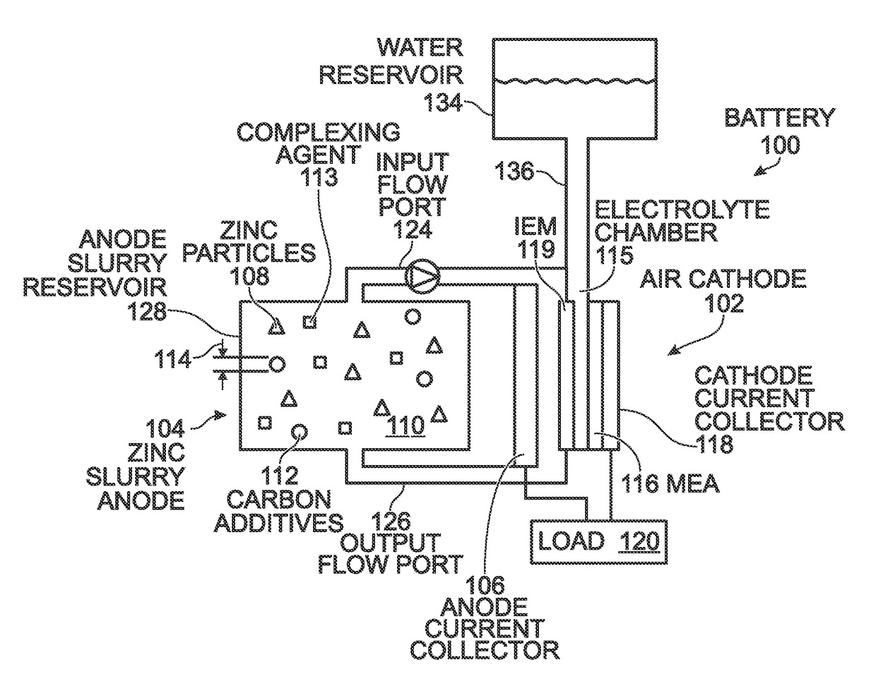
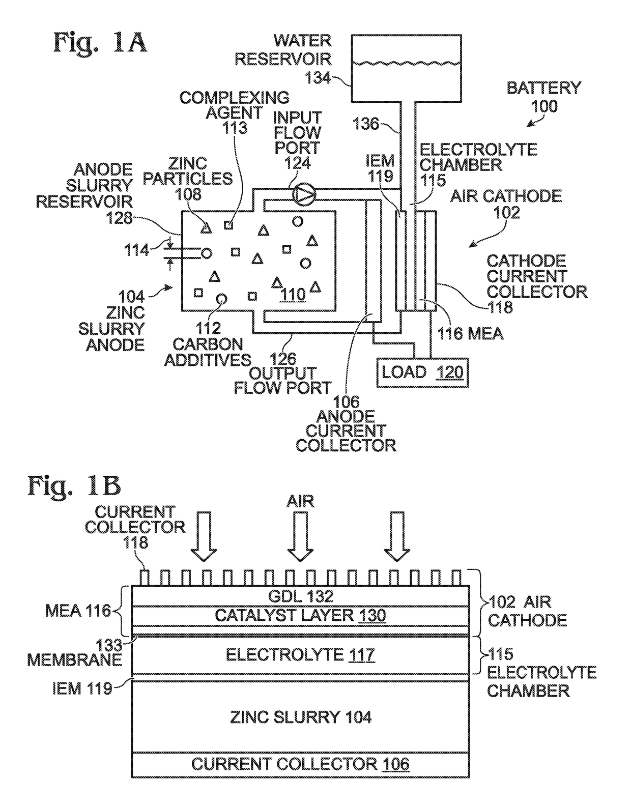
[0020]FIGS. 1A and 1B are, respectively, a partial cross-sectional view of an air cathode battery using a zinc slurry anode with carbon additives, and a detailed view. The battery 100 comprises an air cathode 102 and a zinc slurry anode 104. The zinc slurry anode 104 comprises a current collector 106, zinc particles 108, an alkaline electrolyte 110, with carbon additives 112 and a complexing agent 113 in the alkaline electrolyte 110. Together, the zinc particles 108, alkaline electrolyte 110, complexing agent 113, and carbon additives 112 form a zinc slurry. Typically, the zinc particles 108 have an average size (diameter) 114 in the range of 1 micron to 500 microns. Note: the drawing is not to scale. Alternatively, instead or in addition to Zn, the particles may be magnesium (Mg), aluminum (Al), iron (Fe), copper (Cu), or combinations of these metal particles. An electrolyte chamber 115 comprising alkaline electrolyte 117 is adjacent the air cathode 102, and a water permeable ion-e...


PUM

PropertyMeasurementUnit
molar concentrationaaaaaaaaaa
electrical resistanceaaaaaaaaaa
sizeaaaaaaaaaa

Abstract

An air cathode battery is provided that uses a zinc slurry anode with carbon additives. The battery is made from an air cathode and a zinc slurry anode. The zinc slurry anode includes zinc particles, an alkaline electrolyte, with a complexing agent and carbon additives in the alkaline electrolyte. A water permeable ion-exchange membrane and electrolyte chamber separate the zinc slurry from the air cathode. The carbon additives may, for example, be graphite, carbon fiber, carbon black, or carbon nanoparticles. The proportion of carbon additives to zinc is in the range of 2.5 to 10% by weight. The proportion of alkaline electrolyte in the zinc slurry is in the range of 50 to 80% by volume.

Description

RELATED APPLICATION[0001]The application is a Continuation-in-Part of a pending application entitled, FLOW-THROUGH METAL BATTERY WITH ION EXCHANGE MEMBRANE, invented by Yuhao Lu et al., Ser. No. 14 / 042,264, filed on Sep. 30, 2013;[0002]which is a Continuation-in-Part of a pending application entitled, BATTERY WITH LOW TEMPERATURE MOLTEN SALT (LTMS) CATHODE, invented by Yuhao Lu et al., Ser. No. 13 / 564,015, filed on Aug. 1, 2012. Both these applications are incorporated herein by reference.BACKGROUND OF THE INVENTION[0003]1. Field of the Invention[0004]This invention generally relates to electrochemical cells and, more particularly, to a flow-through air cathode battery using a zinc slurry anode with a carbon additive, complexing agent, and auxiliary water source.[0005]2. Description of the Related Art[0006]Flow-through batteries has been intensively studied and developed for large-scale energy storage due to their long cycle life, flexible design, and high reliability. A battery is ...

Claims


Application Information

Patent Timeline
Patent Type & Authority Patents(United States)
IPC IPC(8): H01M4/38H01M4/76H01M6/50H01M12/06H01M8/04276H01M4/62H01M12/08H01M4/36H01M8/083
CPCH01M4/38H01M4/364H01M4/62H01M4/625H01M4/76H01M6/5077H01M8/04276H01M12/06H01M12/08H01M8/083Y02E60/50
Inventor KISDARJONO, HIDAYATLU, YUHAOLEE, JONG-JANEVANS, DAVIDWANG, LONG
Owner SHARP KK
Why Eureka
Try Eureka