X-ray detection system with improved spatial coverage

a detection system and spatial coverage technology, applied in the field of x-ray detection methods and systems, can solve the problems of missing pixels, not providing a solution, and gaps created between different frames

Pending Publication Date: 2022-08-18
UNIV GENT
View PDF0 Cites 0 Cited by
  • Summary
  • Abstract
  • Description
  • Claims
  • Application Information

AI Technical Summary

Benefits of technology

[0007]It is an object of embodiments of the present invention to provide good methods and systems for X-ray detection with good, e.g. improved, spatial coverage.
[0008]It is an advantage of embodiments of the present invention that the system allows for real-time integration of detector movement information into the acquisition data and processing stream of an X-ray detection recording thus allowing for improving spatial coverage of the X-ray detection system.
[0009]It is an advantage of embodiments of the present invention that imaging can be performed by applying a single shot detection with minimal motion blur due to the high frames per second that can be recorded, balanced with the acquisition times, for direct conversion, spectral or hyperspectral photon counting systems.
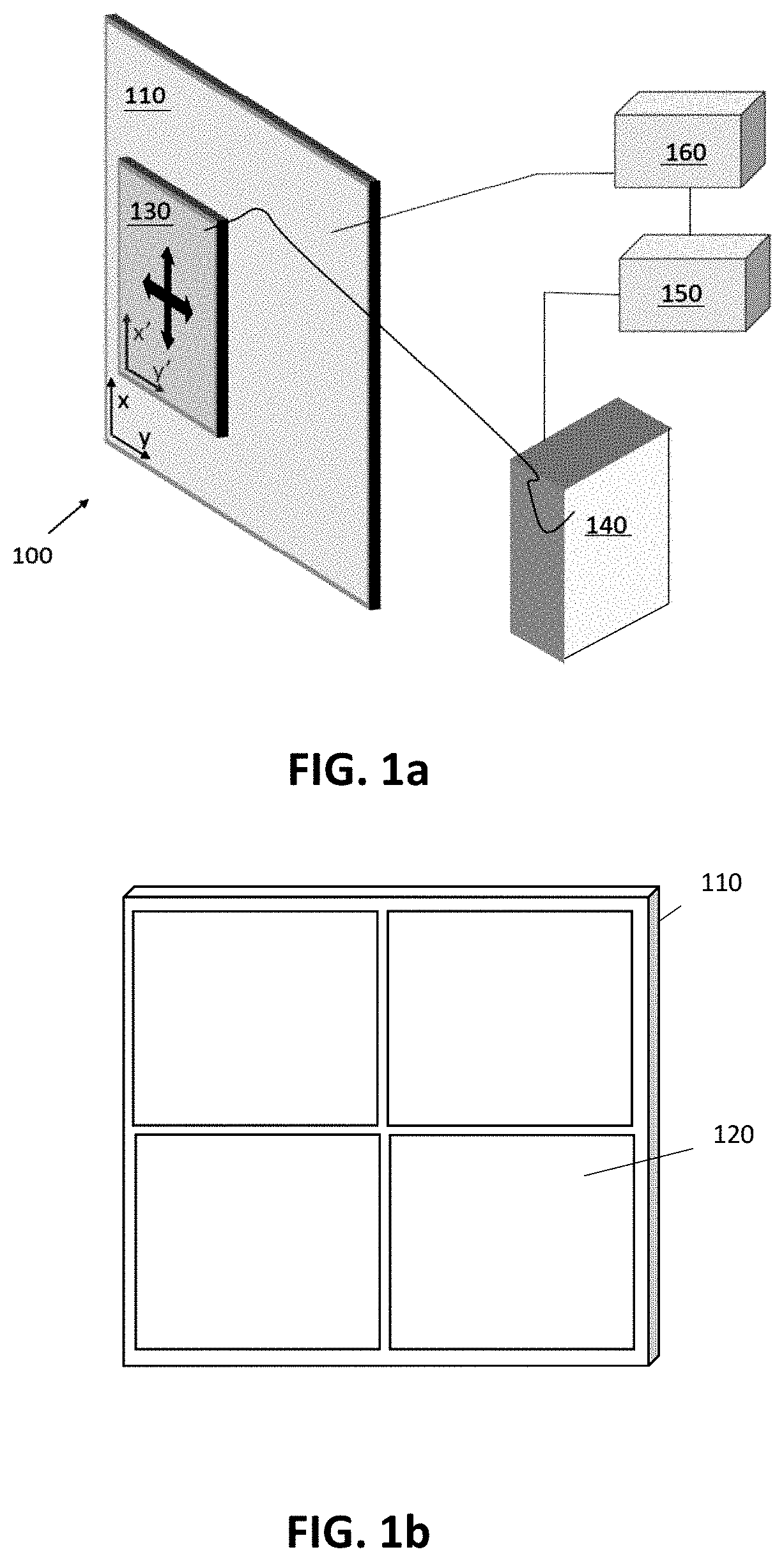
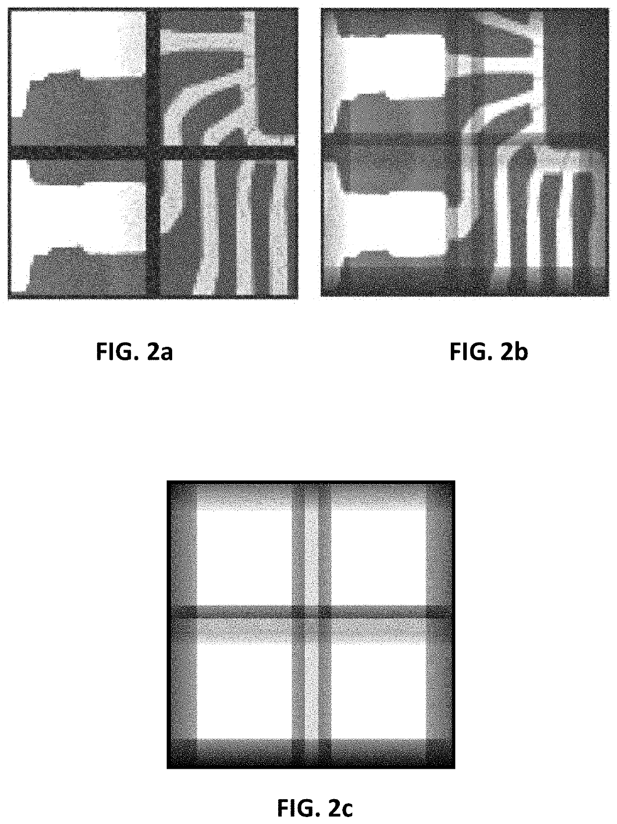
[0026]The present invention also relates to a method for reducing an amount of missing or defective output image data in a solid-state X-ray detection module, the detection module comprising a plurality of detector tiles for directly detecting X-ray radiation, said detector module further comprising a plurality of interstitial areas separating adjacent tiles of the detector module, the method comprising:based on a predetermined field of view for detection and on a predetermined virtual sampling grid comprising a plurality of sampling points defined in a stationary reference frame, determining a trajectory for the detector module and a plurality of detection positions along the trajectory,moving the detector module with the secured detector module in the stationary reference frame in accordance with the determined trajectory, wherein a travel range of the determined trajectory in the stationary reference frame is at least as large as the largest interstitial area,acquiring, during an exposure time for the detector module and whilst moving along the determined trajectory, a plurality of frames at a frame acquisition rate at least a factor of 100, e.g. at least a factor of 1000, faster than the inverse of said exposure time, andcombining the plurality of acquired frames into at least one output image comprising output image data in output image regions associated with the interstitial areas.

Problems solved by technology

The gaps that are created between the different frames nevertheless are an issue to solve.
These gaps can result from missing pixels as well as from different pixel dimensions in this interstitial area.
While this solves the visual disturbance, this does not provide a solution when specific features are present in the regions where the different frames need to be matched with each other.
Nevertheless, typically geometrical effects and edge effects still arise due to the overlap.

Method used


Image

  • X-ray detection system with improved spatial coverage
  • X-ray detection system with improved spatial coverage
  • X-ray detection system with improved spatial coverage

Examples


Embodiment Construction

[0047]The present invention will be described with respect to particular embodiments and with reference to certain drawings, but the invention is not limited thereto but only by the claims.

[0048]The terms first, second and the like in the description and in the claims, are used for distinguishing between similar elements and not necessarily for describing a sequence, either temporally, spatially, in ranking or in any other manner. It is to be understood that the terms so used are interchangeable under appropriate circumstances and that the embodiments of the invention described herein are capable of operation in other sequences than described or illustrated herein.

[0049]Moreover, directional terminology such as top, bottom, front, back, leading, trailing, under, over and the like in the description and the claims is used for descriptive purposes with reference to the orientation of the drawings being described, and not necessarily for describing relative positions. Because component...


PUM


Abstract

An X-ray detection system is described having a solid-state detector module including a plurality of detector tiles at a first side thereof for directly detecting X-ray radiation. The detector module has a plurality of interstitial areas separating adjacent tiles of the detector module, and at least one actuator for inducing motion of the detector module to a plurality of detection positions along a trajectory with respect to a stationary reference frame while the detector module is operated in an exposure mode. The spatial extent of the trajectory in the stationary reference frame is at least as large as the largest interstitial area, and the detector module is adapted for acquiring a plurality of frames in the exposure mode at a frame acquisition rate at least a factor of 100 faster than the inverse of a predetermined exposure time for the exposure mode.

Description

FIELD OF THE INVENTION[0001]The present invention relates to the field of X-ray detection methods and systems. In particular, it relates to X-ray detection methods and systems which improve the spatial coverage of the system by reducing the amount of missing image data and / or by extending the field of view of the detector.BACKGROUND OF THE INVENTION[0002]X-ray detection is widely used in a variety of applications, such as in medical imaging and in material characterization. Depending on the application, large field of view and high resolution are highly relevant requirements. In order to obtain a large field of view or a high pixel count, multi-sensor systems can be used. In multi-sensor detectors, due to the low pixel count of typical direct conversion X-ray sensors, the frames obtained with the different sensors are often stitched to create large-area detectors and increased pixel counts. The gaps that are created between the different frames nevertheless are an issue to solve. Th...

Claims


Application Information

Patent Timeline
Patent Type & Authority Applications(United States)
IPC IPC(8): G01T1/24G01T1/29G06T7/00
CPCG01T1/243G01T1/2985G06T2207/10081G06T2207/10116G06T7/0012
Inventor VAN ASSCHE, FREDERICBOONE, MATTHIEUVANHEULE, SANDER
Owner UNIV GENT
Why Eureka
Try Eureka