
Elastic electrical contact terminal

a technology of electrical contact terminal and electrical contact, which is applied in the direction of dielectric characteristics, connection contact member material, coupling device connection, etc., can solve the problems of high cost of hot-melt adhesive, increased electrical resistance between the object and the electroconductive sheet, and inability to reliably perform electrical connection between objects through the electrical contact terminal

Pending Publication Date: 2022-08-25
JOINSET
View PDF0 Cites 0 Cited by
  • Summary
  • Abstract
  • Description
  • Claims
  • Application Information

AI Technical Summary

Benefits of technology

The present invention is about a new type of electrical contact terminal that is elastic and flexible, and can be used at high temperatures. It also has improved elastic restorability at high temperatures. Additionally, the invention minimizes electrical contact resistance by allowing an electroconductive sheet to directly come into electrical contact with an electroconductive object due to the elasticity of the contact terminal.

Problems solved by technology

Since the hot-melt adhesive is electrically insulated generally, when the hot-melt adhesive high protrudes outward from an outer surface of the electroconductive sheet, while a protruding part comes into contact with an electroconductive object, electrical resistance between the object and the electroconductive sheet increases, and thus, electrical connection between objects through the electrical contact terminal is not reliably performed.
When the hot-melt adhesive is electrically conductive, the hot-melt adhesive is expensive and has a disadvantage that electrical resistance is very higher than the electroconductive sheet.
In addition, since the hot-melt adhesive generally includes thermosetting polymers such as polyurethane and is melted again when heat is applied thereto, it is difficult to maintain adhesion at high temperatures, for example, at 105° C. or higher and thus it is difficult to use the hot-melt adhesive at such temperatures.
Also, there is a disadvantage that it is difficult to economically provide electroconductive contact terminals having a variety of shapes by using only a urethane sponge as an elastic body.

Method used


Image

  • Elastic electrical contact terminal
  • Elastic electrical contact terminal
  • Elastic electrical contact terminal

Examples


Embodiment Construction

[0034]Hereinafter, exemplary embodiments of the present invention will be described in detail with reference to the attached drawings.

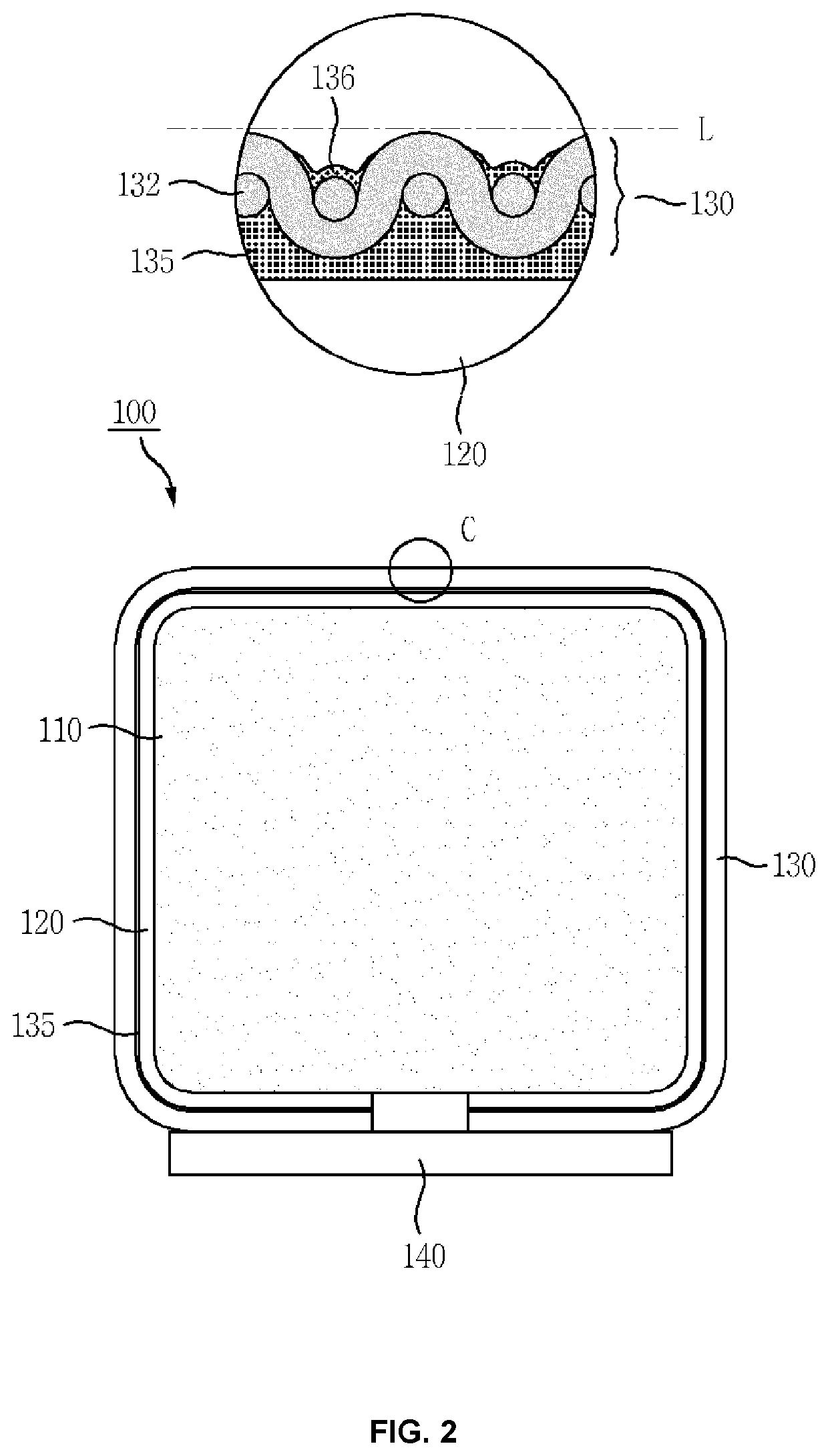
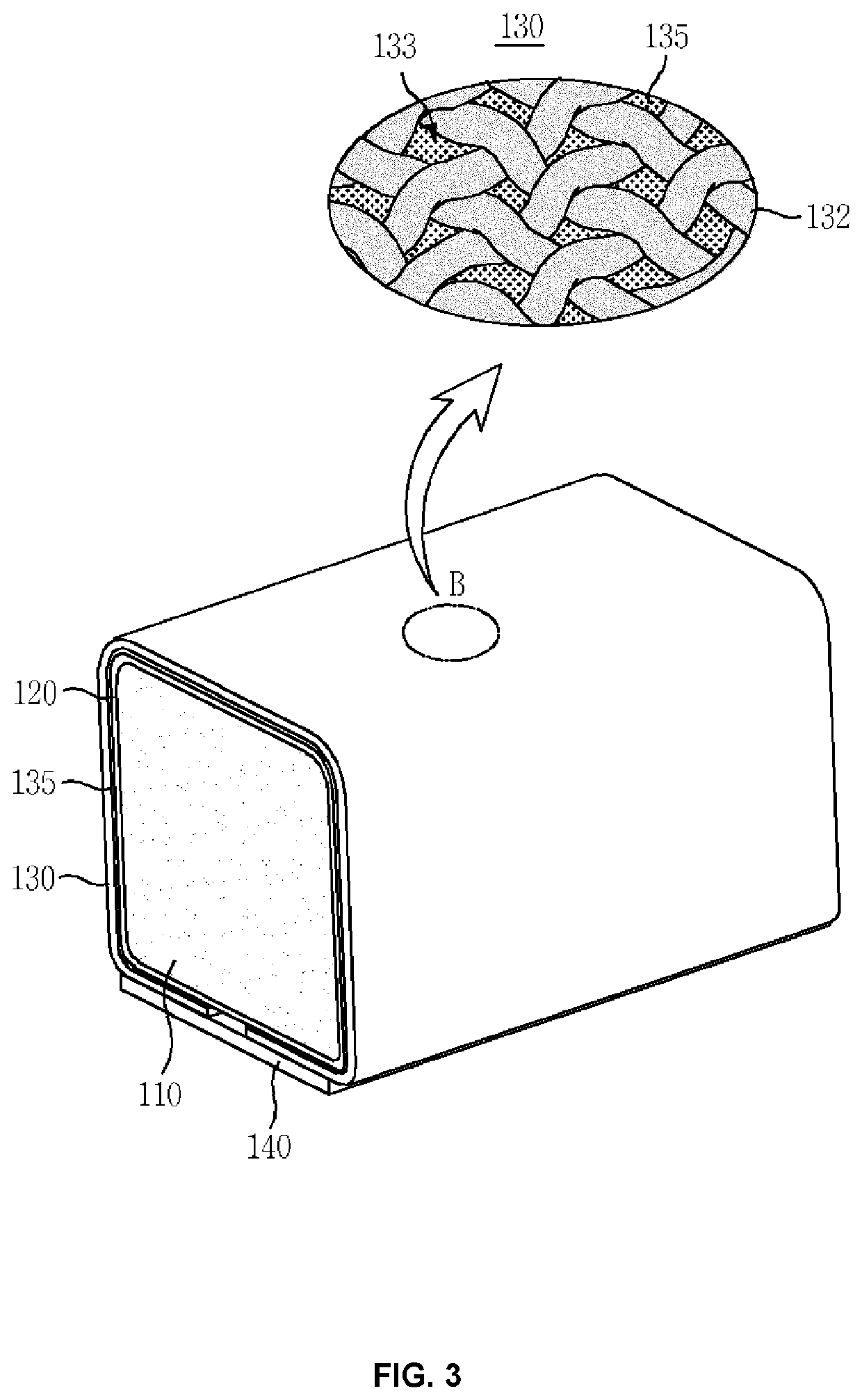
[0035]FIG. 2 is a front view illustrating an example of an electrical contact terminal according to the present invention, and FIG. 3 is a perspective view illustrating an example of the electrical contact terminal according to the present invention.

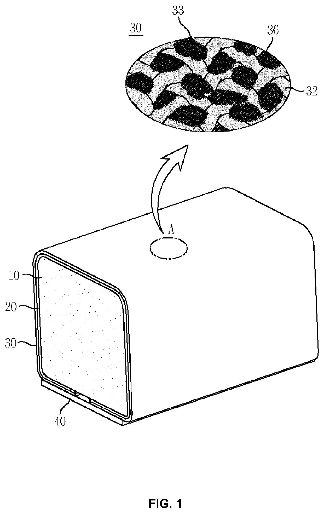
[0036]An electrical contact terminal 100 includes an elastic foam core 110, a silicone rubber adhesive 120 applied to an outer surface of the elastic core 110, and an electroconductive sheet 130 which surrounds the elastic core 110 with the silicone rubber adhesive 120 interposed therebetween and includes a polymer coating layer 135.

[0037]A double-sided electroconductive pressure-sensitive adhesive tape 140 which covers and adheres to a lower surface of the sheet 130 having both spaced ends may be included as necessary.

[0038]The electrical contact terminal 100 to which the adhesive tape 140 adheres may be ...


PUM

PropertyMeasurementUnit
temperaturesaaaaaaaaaa
elasticaaaaaaaaaa
electroconductiveaaaaaaaaaa

Abstract

Disclosed is an elastic electrical contact terminal capable of implementing a reliable electrical connection between objects. The electrical contact terminal comprises: an elastic core; a silicone rubber adhesive applied to the outer surface of the elastic core; and an electrically conductive fiber wrapped around and bonded to the elastic core by means of being interposed with the silicone rubber adhesive, wherein a sheet has a polymer coating layer formed on the inner surface thereof facing the silicone rubber adhesive, and has a metal layer formed on the outer surface thereof.

Description

REFERENCE TO RELATED APPLICATIONS[0001]This is a continuation of International Patent Application PCT / KR2020 / 015853 filed on Nov. 12, 2020, which designates the United States and claims priority of Korean Patent Application No. 10-2019-0146590 filed on Nov. 15, 2019, the entire contents of which are incorporated herein by reference.FIELD OF THE INVENTION[0002]The present invention relates to an elastic electrical contact terminal, and more particularly, to an elastic electrical contact terminal capable of implementing a reliable electrical connection between objects with elasticity and having less electrical contact resistance to facing objects.BACKGROUND OF THE INVENTION[0003]In general, an elastic electrical contact terminal should have excellent electrical conductivity and elasticity and is fixed to a printed circuit board through soldering or using a double-sided electroconductive pressure-sensitive adhesive tape.[0004]FIG. 1 illustrates an example of a conventional electrical c...

Claims


Application Information

Patent Timeline
Patent Type & Authority Applications(United States)
IPC IPC(8): H01R13/24H01R4/58
CPCH01R13/2414H01R4/58H05K3/4015H05K2201/0133
Inventor KIM, SUN-KI
Owner JOINSET
Learn More