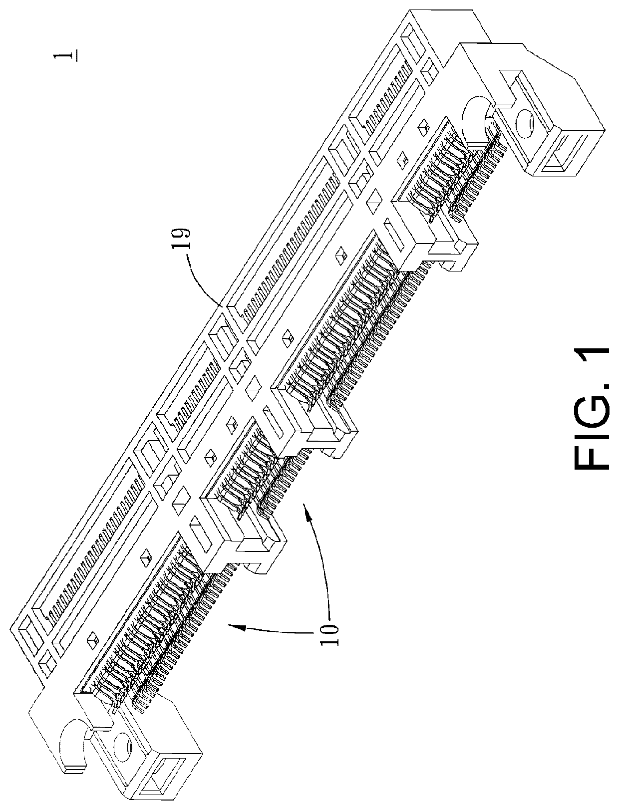
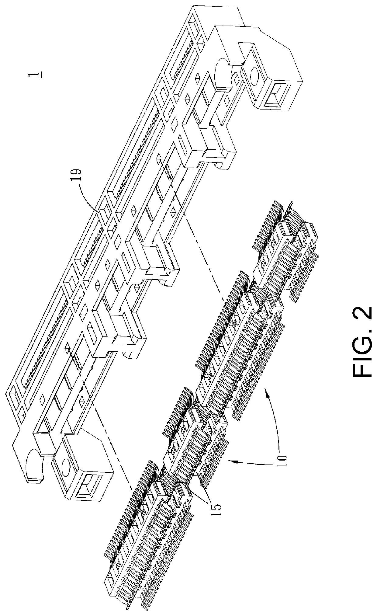
Electrical connector

a technology of electrical connectors and connectors, applied in the direction of coupling device connections, electrical equipment, coupling protection earth/shielding arrangements, etc., can solve the problems of inductive and capacitive coupling between signal wires and interferences, affecting the high-speed transmission of data, loss of data transmission and transmission errors

Pending Publication Date: 2022-08-25
DONGGUAN LUXSHARE TECH CO LTD
View PDF30 Cites 0 Cited by
  • Summary
  • Abstract
  • Description
  • Claims
  • Application Information

AI Technical Summary

Benefits of technology

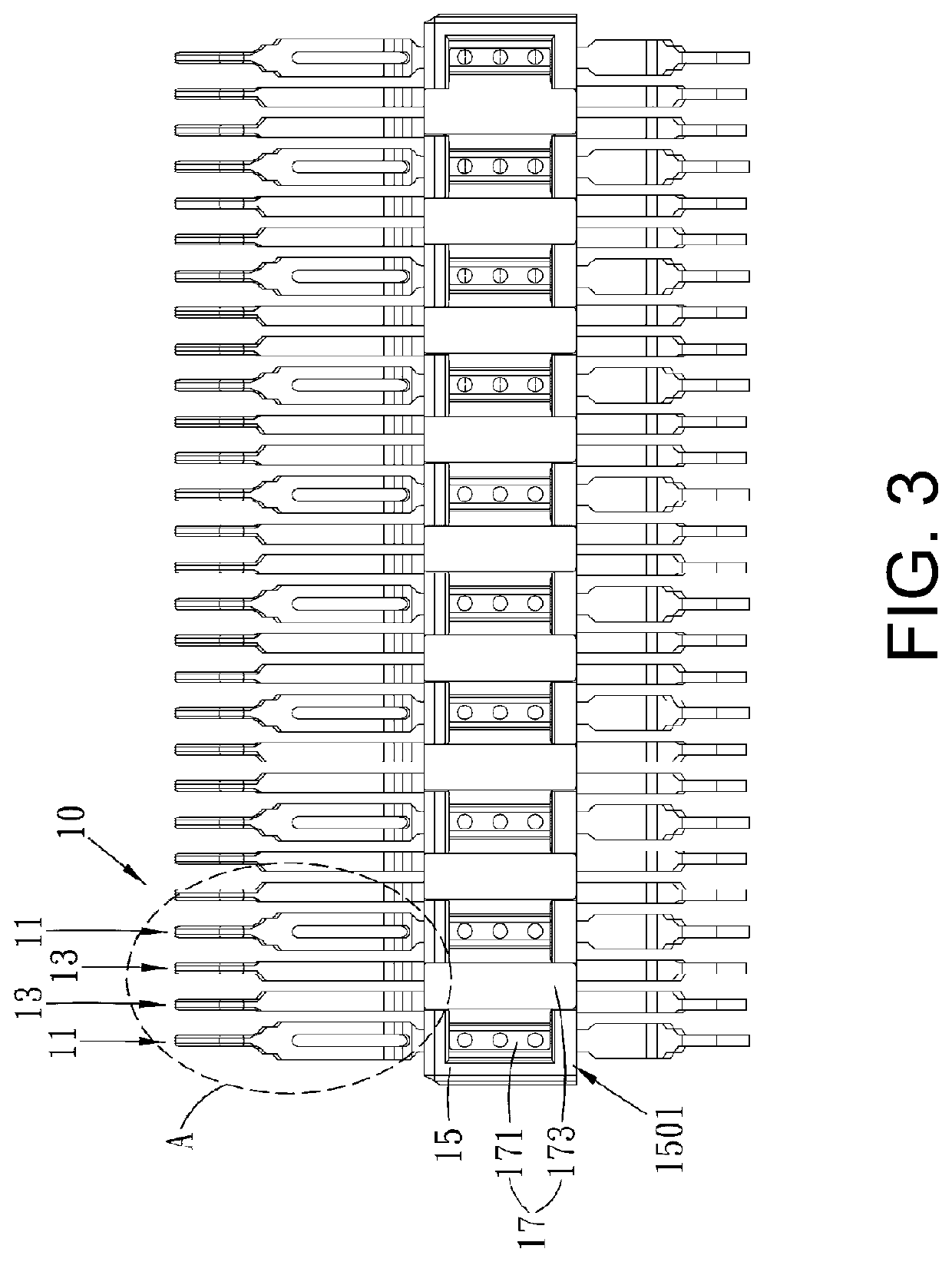
[0006]In the embodiments of the present disclosure, by increasing the outer diameter of the first contacting part of the ground terminal to be greater than the outer diameter of the second contacting part of the signal terminal, the outer diameter of the first contacting part of the ground terminal can be increased to shorten the distance between the second contacting part of the signal terminal and the first contacting part of the adjacent ground terminal. In this way, the return path for the signal terminal can be shorter, and more energy can be bound between the signal terminal and the ground terminal to avoid excessive interference from the surrounding magnetic field. Thus, the crosstalking among signal terminals can be effectively handled.

Problems solved by technology

In the prior arts, crosstalking is one of the critical issues to consider for designing electrical connectors, which is the coupling of two signal wires since the spatial distance between the two signal wires is too close, leading to inductive and capacitive coupling among signal wires and interferences thereby.
Crosstalking is a type of interference energy value caused by the coupling of one signal to another signal, which could affect the high-speed transmission of data.
Inductive signals may cause loss of data transmission and transmission errors.
Thus, dealing with crosstalking effectively is one of the main issues to be considered for electrical connector designing.

Method used


Image

  • Electrical connector
  • Electrical connector
  • Electrical connector

Examples


Embodiment Construction

[0024]The present disclosure will now be described more fully hereinafter with reference to the accompanying drawings, in which exemplary embodiments of the disclosure are shown. This present disclosure may, however, be embodied in many different forms and should not be construed as limited to the embodiments set forth herein. Rather, these embodiments are provided so that this present disclosure will be thorough and complete, and will fully convey the scope of the present disclosure to those skilled in the art.

[0025]Certain terms are used throughout the description and following claims to refer to particular components. As one skilled in the art will appreciate, manufacturers may refer to a component by different names. This document does not intend to distinguish between components that differ in name but function. In the following description and in the claims, the terms “include / including” and “comprise / comprising” are used in an open-ended fashion, and thus should be interprete...


PUM


Abstract

An electrical connector comprising a terminal module, which comprises a ground terminal and a signal terminal disposed side by side with the ground terminal. The ground terminal comprises a first contacting part. The signal terminal comprises a second contacting part. An outer diameter of the first contacting part is greater than an outer diameter of the second contacting part. The contacting end of the ground terminal is wider than the contacting end of the signal terminal. By increasing the width of the contacting end of the ground terminal, the distance between the contacting end of the signal terminal and the contacting end of the adjacent ground terminal can be shortened. In this way, the return path for the signal terminal can be shorter, and more energy can be bound between the signal terminal and the ground terminal to avoid excessive interference from the surrounding magnetic field.

Description

CROSS-REFERENCE TO RELATED APPLICATION[0001]This application claims the priority benefit of Chinese Patent Application Serial Number 202110189332.9, filed on Feb. 19, 2021, the full disclosure of which is incorporated herein by reference.BACKGROUNDTechnical Field[0002]The present disclosure relates to the technical field of connector, particularly to an electrical connector.Related Art[0003]In the prior arts, crosstalking is one of the critical issues to consider for designing electrical connectors, which is the coupling of two signal wires since the spatial distance between the two signal wires is too close, leading to inductive and capacitive coupling among signal wires and interferences thereby. Capacitive coupling causes coupling current, while inductive coupling causes coupling voltage. Crosstalking is a type of interference energy value caused by the coupling of one signal to another signal, which could affect the high-speed transmission of data. The source of crosstalking is ...

Claims


Application Information

Patent Timeline
Patent Type & Authority Applications(United States)
IPC IPC(8): H01R13/6471H01R13/6474
CPCH01R13/6471H01R13/6474H01R13/652H01R13/6461
Inventor CHEN, HONGJICHENG, HENGSHANHE, YUNFENG
Owner DONGGUAN LUXSHARE TECH CO LTD
Why Eureka
Try Eureka