Wind Pressure-Driven Air Intake Device

a technology of air intake device and air intake valve, which is applied in the direction of lighting and heating apparatus, ventilation system, heating type, etc., can solve the problems of lack of prior art, lack of disclosure, general lack of structural features and mechanisms, etc., and achieves the effects of low manufacturing cost, zero power consumption, and convenient installation

Pending Publication Date: 2022-09-08
LIN JASON
View PDF7 Cites 0 Cited by
  • Summary
  • Abstract
  • Description
  • Claims
  • Application Information

AI Technical Summary

Benefits of technology

The patent describes an aerodynamic device that captures wind pressure and redirects it into a space that needs ventilation, without the need for a powered air driver. The device comprises multiple abutting wind collectors with one-way inflow valves that only allow inward flow into the central chamber. The device can be used in buildings, vehicles, and other enclosed spaces, and it requires no power consumption. It is simple, lightweight, and inexpensive to manufacture and install. The technical effects of the patent are that it provides a foolproof air intake that ensures a positive pressure at the inlet, regardless of external wind conditions, and it offers an effective and efficient solution for air intake without the need for moving parts or power consumption. Additionally, the device can be mounted on any surface shape and slope as required.

Problems solved by technology

This leads to a challenge of turning such uncertainties into a certainty of an intake being always an intake, and not being nullified or even adversely becoming an unwanted exhaust outlet.
No prior art is found by this inventor that overcomes such a challenge for an air intake without the assistance of a powered air driver or a moving vehicle / carrier.
All these disclosures, however, generally lack structural features and mechanism that overcome the above-mentioned challenge for an air intake.

Method used


Image

  • Wind Pressure-Driven Air Intake Device
  • Wind Pressure-Driven Air Intake Device
  • Wind Pressure-Driven Air Intake Device

Examples


Embodiment Construction

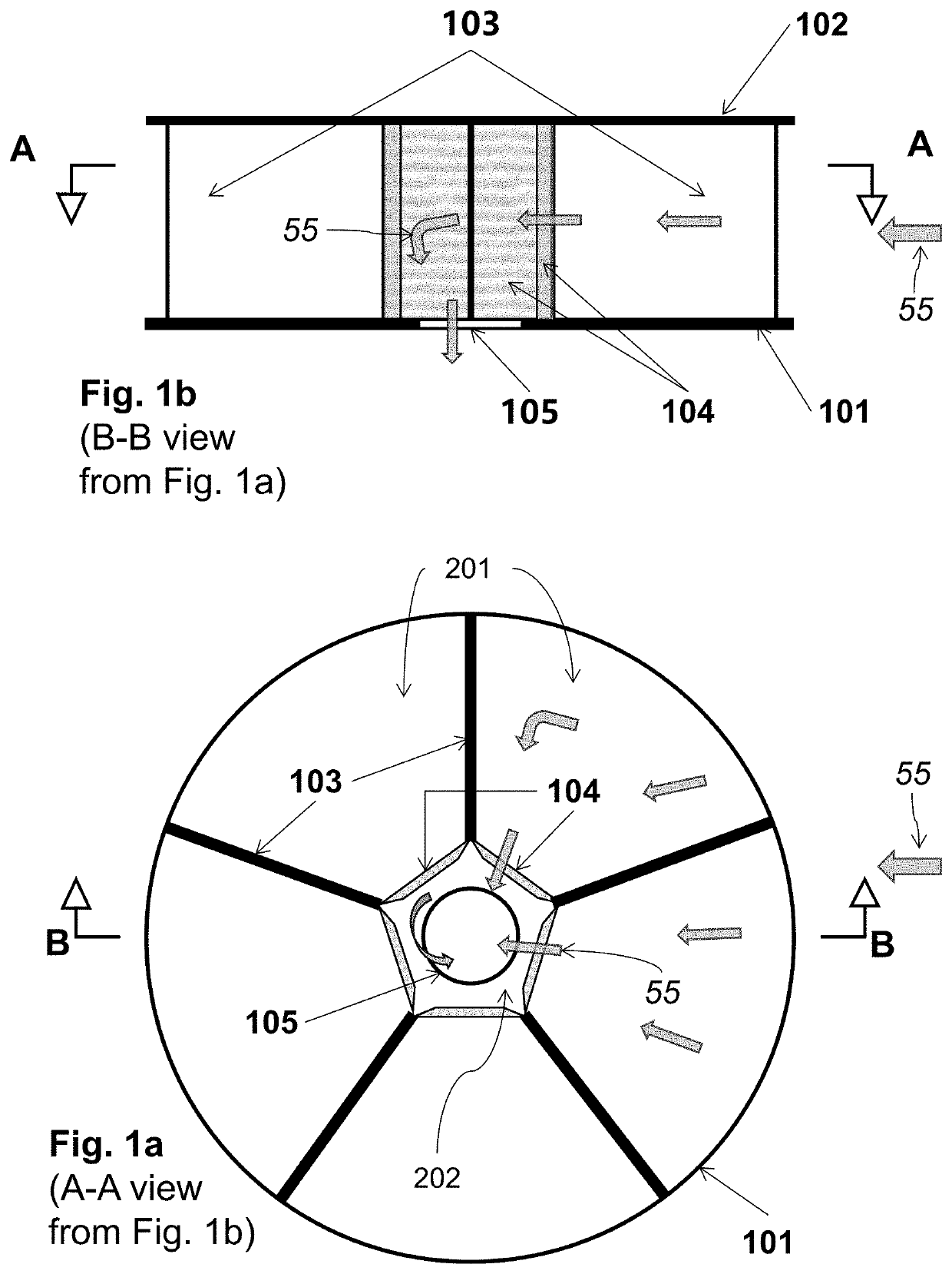
[0021]One embodiment of the general concept has been depicted in FIGS. 1a and 1b, where abutting wind collectors 201 are all arranged to lie between two planar surfaces. Nevertheless, they can be arranged in other fashions according to the spirit of this invention, for example, collectively forming a cube, a spherical or part-spherical body, with some tunnels' longitudinal axes oriented out of plane, say outwardly upwards, or even downwards (if the collective body is raised from a mounting surface with an elongate hollow support that also serves as a conduit for air flow, depending on the use scenario). However, for uses on an open surface, whether a rooftop or a wall, a coplanar or in-plane arrangement is considered more cost effective due to its relative simplicity, since wind flow around a building, or around any enclosed object, is primarily along or in parallel with the building's surfaces, and off-surface or off-plane wind collectors can make contributions only in a very limit...


PUM


Abstract

This application discloses a wind pressure-driven air intake device for natural ventilation of zero power consumption. Such a device comprises multiple tunnels being arranged around a common central chamber, each having an inflow valve at its inner end connecting the central chamber and an outer end open to ambient airflow. The inflow valve allows only inward flow from a corresponding tunnel into the central chamber. The central chamber has an opening allowing airflow exit to a space to be ventilated. The device is capable of capturing ambient wind flow and wind pressure to be fed to the vented space regardless of wind flow direction towards the device, with no need for a powered air driver.

Description

1. CROSS-REFERENCE TO RELATED APPLICATIONS[0001]This application is entitled to the benefit of a China patent application: Patent No. ZL 2020 2 0003740.1, Publication Date 2020 Aug. 11, Publication No. CN 211233238 U, patent application filed 2020 Jan. 2.BACKGROUND[0002]Field of Invention[0003]This invention relates to an air intake device, which can be utilized in the field of air ventilation for buildings, industrial and agricultural facilities and vehicles.Discussion of Prior Art[0004]In ventilation, besides exhaust outlets, air inlets or air intakes are also essential. Their aerodynamic characteristics are important to their performance, particularly for natural ventilation, where no powered air driver, such as an electric fan or blower, is required or used, and where an air intake relies on uncertain external wind flow that can come in one of many possible directions and in different strengths. This leads to a challenge of turning such uncertainties into a certainty of an intak...

Claims


Application Information

Patent Timeline
IPC IPC(8): F24F7/02
CPCF24F7/02F24F13/06
Inventor LIN, JASON
Owner LIN JASON
Why Eureka
Try Eureka