Supercharge Your Innovation With Domain-Expert AI Agents!

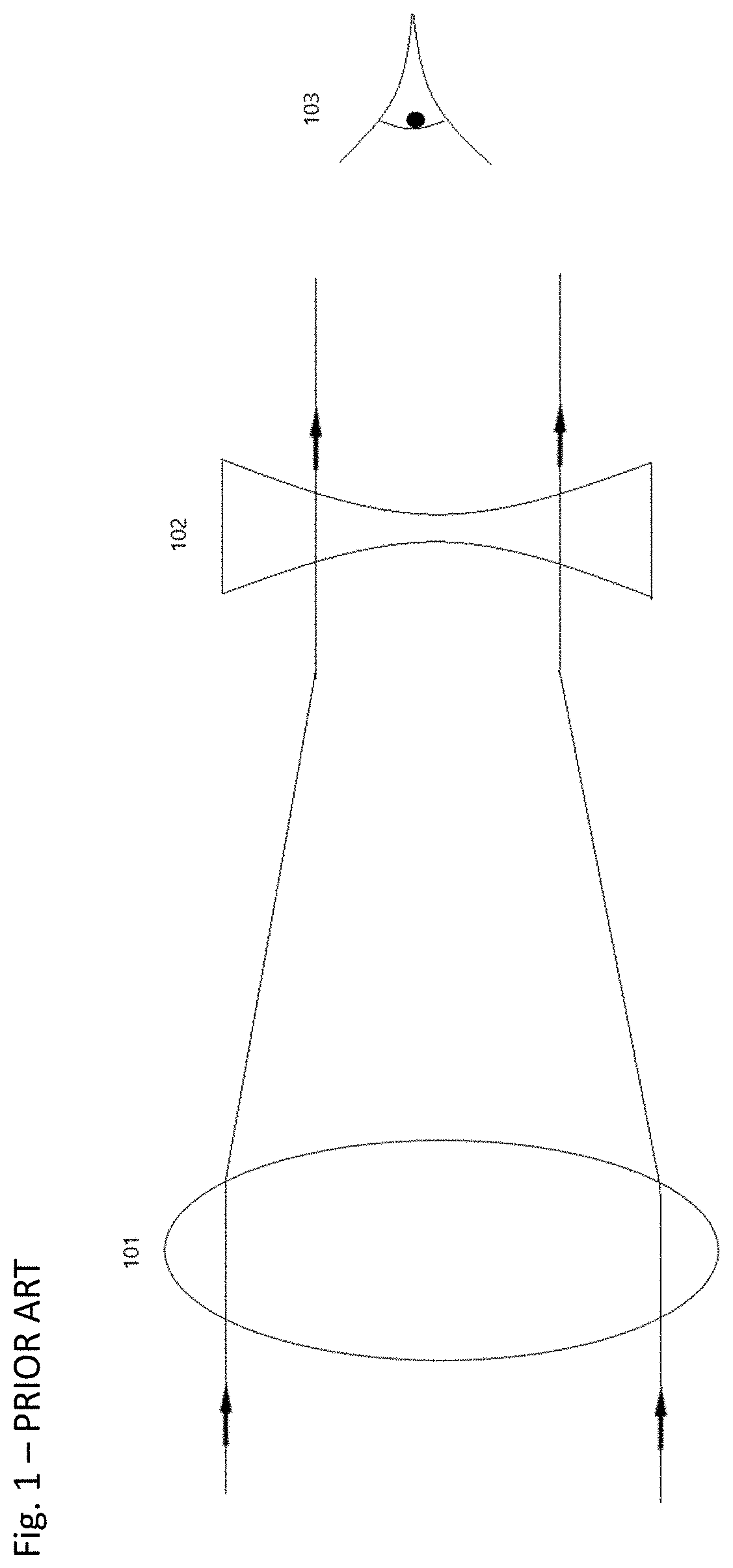
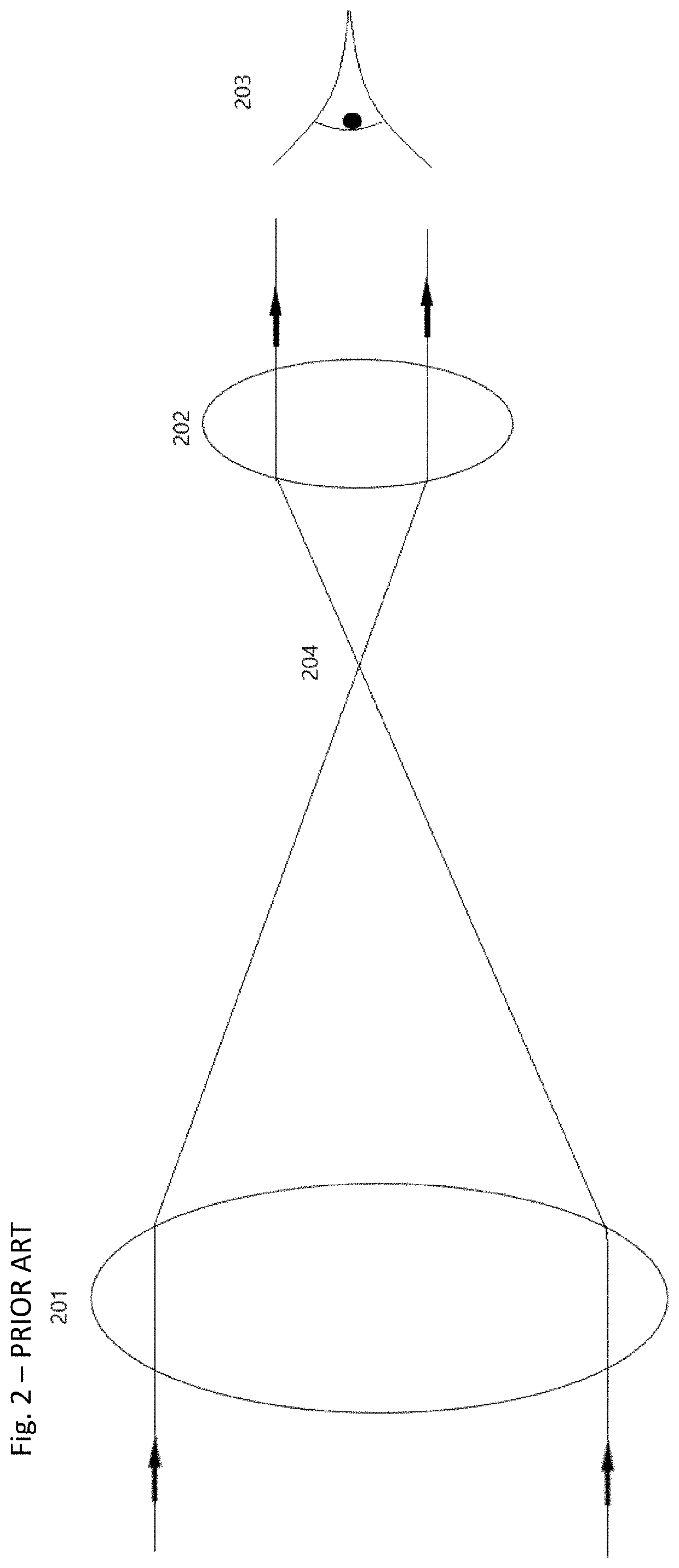
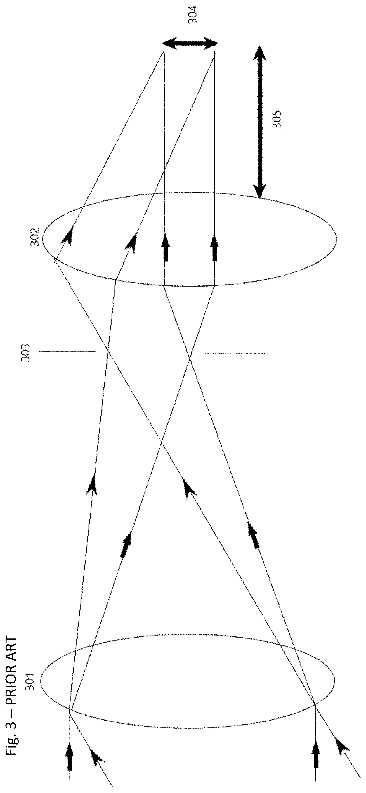
Reticle overlaid within a galilean magnification system

a technology of magnification system and telescope, applied in the field of optical system, can solve the problems of limited maximum fov viewable by the eye in the galilean telescope, increased magnification of the telescope device, and increased magnification of the telescope device, and achieve the effect of low magnification

Pending Publication Date: 2022-09-08
TRULIFE OPTICS LTD
View PDF0 Cites 0 Cited by
  • Summary
  • Abstract
  • Description
  • Claims
  • Application Information

AI Technical Summary

Benefits of technology

This patent describes an optical system which includes a compact low magnification Galilean telescope with a reticle integrated within. The reticle is generated using a hologram and is set at the correct focal plane using the objective and eyepiece lenses. The system uses an off-axis source and redirects the light on-axis to fill a gap in the market for a small system with a parallax-free holographic reticle. Additionally, the patent discusses a pre-compensated reflex sight or "birdbath" arrangement which uses a partially transparent concave mirror to reflect reticle light towards the eyepiece lens and applies optical power to the reflected light to pre-compensate it for the eyepiece lens. The technical effects of the invention are a small and compact optical system with a reticle integrated within and a pre-compensated reflex sight for improved targeting accuracy.

Problems solved by technology

The maximum FOV viewable by the eye in a Galilean telescope is limited.
This becomes a greater issue as the magnification of the telescope device increases.
Nonetheless, a low magnification Galilean system has a very large effective exit pupil and the Keplerian external exit pupil can make it hard to position the user's eye correctly to see the whole FOV.
As noted in “Practical optical system layout”, Warren J. Smith, McGraw-Hill (1997) “another limitation of the Galilean is that, since there is no internal focal point, a crosshair or reticle cannot be used; the Kepler or terrestrial forms are used when a reticle is needed”.
Such approaches make the optical system, comprising the magnification device and the reticle device bulky.
Otherwise, the eye relief may be unsuitable for use (if the telescope is in front of the red dot).
The separate magnifier is also bulky due to the use of two separate components (red dot and magnifier).
The combination of the length of a holographic reticle and magnifier is too long and bulky for many applications.
This may hinder target acquisition, if the reticle is larger than the target at the focal plane distance.
However, this design does not realise any of these potential advantages suggested above, as the distance between the reticle and the beamsplitter can be significant and the resultant system consequently remains bulky.

Method used


Image

  • Reticle overlaid within a galilean magnification system
  • Reticle overlaid within a galilean magnification system
  • Reticle overlaid within a galilean magnification system

Examples


second embodiment

[0082]Some variations on these basic embodiments are possible, for example using a holographic transparent waveguide to transfer the light. Referring next to FIG. 10, there is depicted a schematic configuration for applying a holographic reticle to a Galilean magnification system in accordance with a This configuration comprises: an eyepiece lens 801; an objective lens 802; an object 803; a lens 804; a holographic incoupler 805; a holographic outcoupler 806; and a waveguide 807. The waveguide 807 is incorporated within the Galilean telescope formed by the eyepiece lens 801 and the objective lens 802. Light from the object 803 is collimated by the lens 804 and coupled into the waveguide 807 (a glass substrate) by the holographic incoupler 805, which diffracts the light at an angle greater than the critical angle for Total Internal Reflection (TIR). The incoupled light propagates along the waveguide 807 and is then outcoupled by holographic outcoupler 806. Typically, an outcoupler wo...

third embodiment

[0084]An example of this is now considered with reference to FIG. 11, in which there is depicted a schematic configuration for applying a holographic reticle to a Galilean magnification system in accordance with a This configuration comprises: an objective lens 901; an eyepiece lens 902; an object 903; a lens 904; a holographic incoupler 905; a holographic outcoupler 906; and a waveguide 907. The operation of this configuration is very similar to that discussed above, with reference to FIG. 10. This configuration allows a reverse Galilean telescope (in which user views through the “reverse” side of the telescope), for use in a camera viewfinder or similar, comprising the objective lens 901 and the eyepiece lens 902. The waveguide 907 is configured and acts as discussed with regard to the waveguide 807 in FIG. 10, but the holographic outcoupler 906 diverges the outcoupled light, which is then compensated for by the (positive) eyepiece lens 902, to provide a virtual image at the corr...


PUM


Abstract

An optical system is provided, including a Galilean magnification device, including an objective lens and an eyepiece lens arranged along an axis. One of the objective lens and the eyepiece lens is a positive lens and the other is a negative lens, thereby defining an image working distance; a reticle device within the Galilean magnification device, including a holographic element, the reticle device being configured to receive light for illuminating the holographic element from off the axis and to direct light from the holographic element on the axis, so that light from the holographic element is set at the image working distance by the eyepiece lens. There is also described a method for recording a holographic reticle for use in a Galilean magnification device.

Description

CROSS REFERENCE TO RELATED APPLICATION[0001]This application claims the benefit under 35 U.S.C. § 119(a) of United Kingdom Application No. GB 2020012.7 filed Dec. 17, 2020, the contents of which are incorporated by reference herein in their entirety.BACKGROUND OF THE DISCLOSURE1. Field of the Disclosure[0002]The disclosure concerns an optical system that may form part of an optical device with magnification optics, for example a Galilean telescopic gun sight incorporating a targeting holographic reticle or a reticle device based on a concave mirror with optical power.2. Description of the Related Art[0003]The basic design of a magnifying device depends on the user's application, but typically requires at least two lenses, one lens referred to as the objective lens (oriented towards the real world, where the real world is referred to as the object) and one lens referred to as the eyepiece lens (oriented towards the user's eye, or a camera). The magnified view of the real world as vie...

Claims


Application Information

Patent Timeline
IPC IPC(8): F41G1/38G02B25/00G02B9/10F41G1/30G02B5/32
CPCF41G1/38G02B25/001G02B9/10F41G1/30G02B5/32G02B27/32G03H1/0005G03H1/02G03H1/0402G03H1/0465G03H2001/0473G02B27/34
Inventor VOLKOV, ANDRII
Owner TRULIFE OPTICS LTD
Features
  • R&D
  • Intellectual Property
  • Life Sciences
  • Materials
  • Tech Scout
  • Unparalleled Data Quality
  • Higher Quality Content
  • 60% Fewer Hallucinations
Learn More