Method and system for variable optical thickness waveguides for augmented reality devices

a technology of optical thickness and augmented reality, applied in the field of method and system of variable optical thickness waveguide for augmented reality devices, to achieve the effect of improving the quality of virtual conten

Pending Publication Date: 2022-09-08
MAGIC LEAP
View PDF7 Cites 3 Cited by
  • Summary
  • Abstract
  • Description
  • Claims
  • Application Information

AI Technical Summary

Benefits of technology

[0013]Numerous benefits are achieved by way of the present invention over conventional techniques. For example, embodiments of the present invention provide methods and systems that can improve the quality of virtua

Problems solved by technology

Because the human visual perception system is complex, it is challenging to produce AR technology that facilitates a comfo

Method used


Image

  • Method and system for variable optical thickness waveguides for augmented reality devices
  • Method and system for variable optical thickness waveguides for augmented reality devices
  • Method and system for variable optical thickness waveguides for augmented reality devices

Examples


Embodiment Construction

[0134]Reference will now be made to the drawings, in which like reference numerals refer to like parts throughout. Unless indicated otherwise, the drawings are schematic not necessarily drawn to scale.

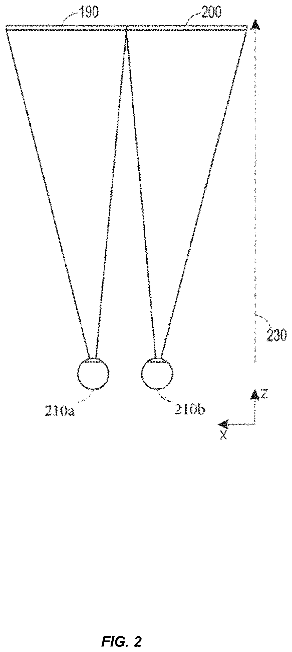
[0135]FIG. 2 illustrates a conventional display system for simulating three-dimensional imagery for a user. It will be appreciated that a user's eyes are spaced apart and that, when looking at a real object in space, each eye will have a slightly different view of the object and may form an image of the object at different locations on the retina of each eye. This may be referred to as binocular disparity and may be utilized by the human visual system to provide a perception of depth. Conventional display systems simulate binocular disparity by presenting two distinct images 190, 200 with slightly different views of the same virtual object-one for each eye 210a, 210b corresponding to the views of the virtual object that would be seen by each eye were the virtual object a real object at...


PUM


Abstract

An augmented reality device includes a projector, projector optics optically coupled to the projector, and an eyepiece optically coupled to the projector optics. The eyepiece includes an eyepiece waveguide characterized by lateral dimensions and an optical path length difference as a function of one or more of the lateral dimensions.

Description

CROSS-REFERENCES TO RELATED APPLICATIONS[0001]This application is a continuation in part of U.S. patent application Ser. No. 17 / 308,407, filed on May 5, 2021, entitled “BIASED TOTAL THICKNESS VARIATIONS IN WAVEGUIDE DISPLAY SUBSTRATES,” which is a continuation of U.S. patent application Ser. No. 16 / 792,083, filed on Feb. 14, 2020, entitled “BIASED TOTAL THICKNESS VARIATIONS IN WAVEGUIDE DISPLAY SUBSTRATES,” now U.S. Pat. No. 11,022,753, issued on Jun. 6, 2021, which claims priority to U.S. Provisional Patent Application No. 62 / 820,769, filed on Mar. 19, 2019, and U.S. Provisional Patent Application No. 62 / 805,832, filed on Feb. 14, 2019, the disclosures of which are hereby incorporated by reference in their entirety for all purposes.BACKGROUND OF THE INVENTION[0002]Modern computing and display technologies have facilitated the development of systems for so called “virtual reality” or “augmented reality” experiences, wherein digitally reproduced images or portions thereof are present...

Claims


Application Information

Patent Timeline
IPC IPC(8): G02B6/13G02B6/122G02B26/08F21V8/00
CPCG02B6/13G02B6/122G02B6/1221G02B26/0891G02B6/0046G02B2006/12038G02B27/0172G02B27/0081G02B5/1814G02B27/4272G02B2006/12197G02B2006/12069G02B2006/12061
Inventor TEKOLSTE, ROBERT D.ONG, RYAN JASONLIU, VICTOR KAIBHARGAVA, SAMARTHPEROZ, CHRISTOPHESINGH, VIKRAMJITMENEZES, MARLON EDWARDYANG, SHUQIANGXU, FRANK Y.
Owner MAGIC LEAP
Why Eureka
Try Eureka