Soap Holder
- Summary
- Abstract
- Description
- Claims
- Application Information
AI Technical Summary
Benefits of technology
Problems solved by technology
Method used
Image

Examples
first embodiment
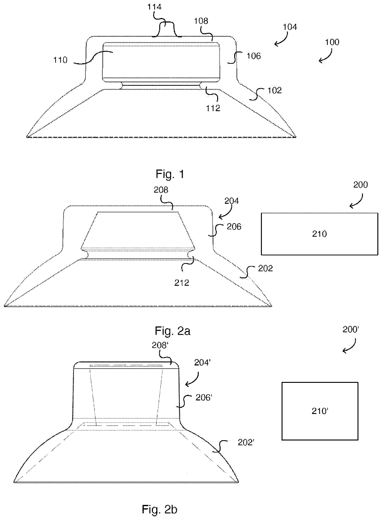
[0058]FIG. 1 shows the soap holder device 100 according to the invention in a sectional view. A suction cup 102 is formed in the lower region of the soap holder 100. The thickness of the suction cup 102 decreases in a radially outward direction. This has the advantage that the suction cup 102 comprises, on the one hand, sufficient stability to support heavy loads and, on the other hand, sufficient flexibility to conform to a surface of a body. Extending upwardly in the axial direction from the suction cup 102 is a wall portion 106 which is substantially cylindrical in shape. A roof portion 108 is formed above the wall portion 106, which forms a downwardly open cylinder with the wall portion 106. A sealing lip 112 extends radially inwardly from the upper end of the suction cup 102.
[0059]A first magnetic element 110 is disposed within the wall portion 106, the roof portion 108, and the sealing lip 112. In a preferred embodiment, the first magnetic element 110 is a permanent magnet.
[00...
second embodiment
[0068]FIG. 2a shows the soap holder 200 having a suction cup 202, a sealing lip 212, a wall portion 206, and a roof portion 208, which is substantially structurally the same as the embodiment previously described with reference to FIG. 1. The wall portion 206 is tapered such that in the axial upward direction, the thickness of the wall portion increases, with the wall portion 206 being formed cylindrically in its outer contour. In other words, in the axial upward direction, the inner radius of the wall portion decreases. If a cylindrical first magnetic member 210 is pushed between the wall portion 206, the wall portion 206 is biased such that it elastically contracts. Thus, a higher holding force is achieved.
[0069]FIG. 2b shows an modification of the second embodiment of the soap holder 200′ having a suction cup 202′, a wall portion 206′ and a roof portion 208′, which is substantially structurally the same as the embodiment previously described with reference to FIG. 1. The wall por...
fifth embodiment
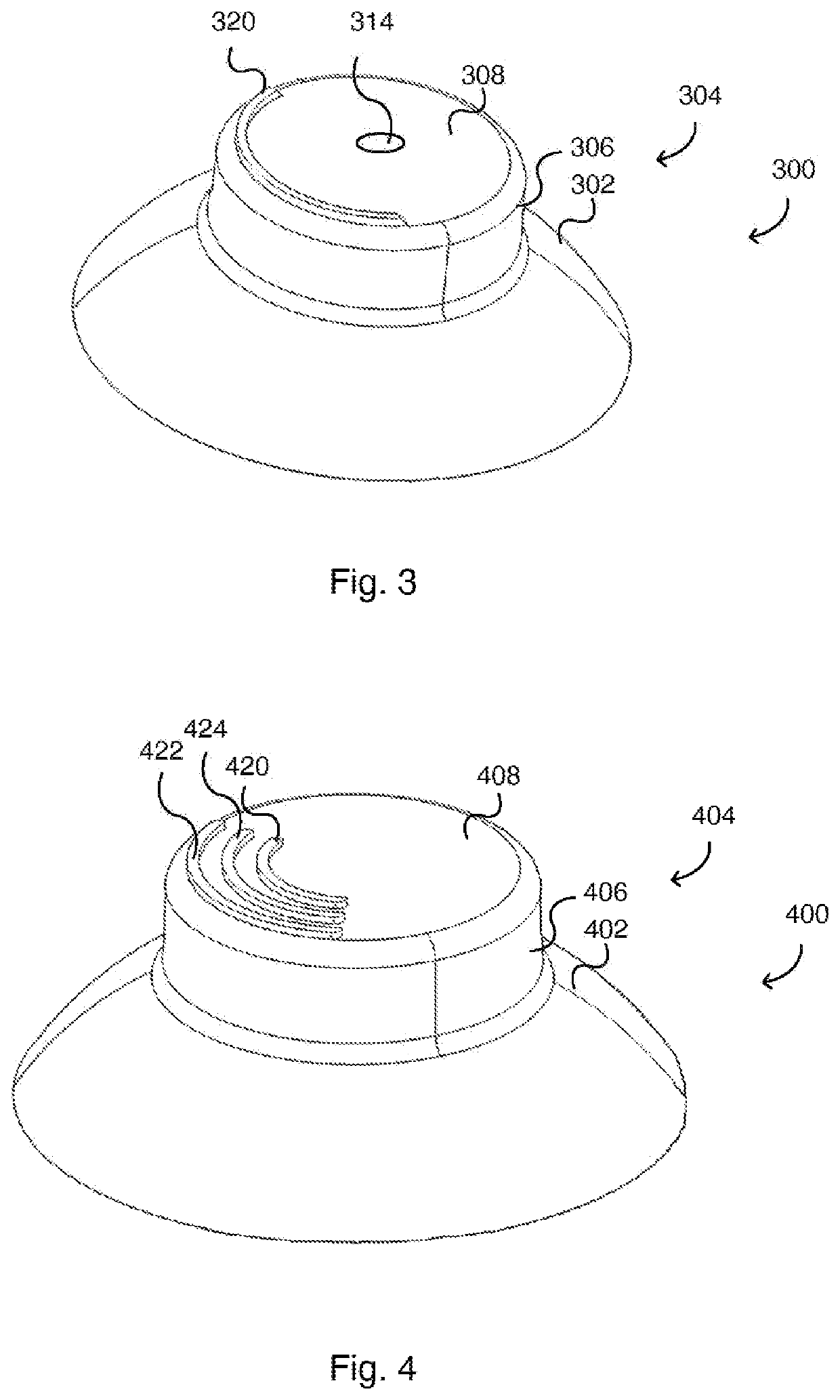
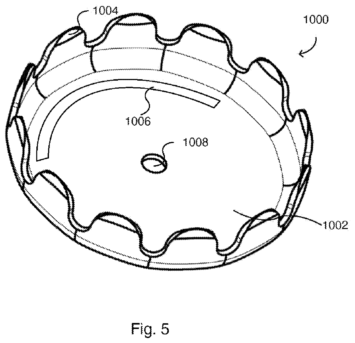
[0074]At the roof region, a protrusion 514 may extend in the axial direction away from the second region 504, which, in use, extends into the opening 1008 in the disk 1002 of the second magnetic element 1000. It will be understood that in the fifth embodiment, the ridges 320, 420, 422, 424 shown in FIGS. 3 and 4 may alternatively or additionally be formed on the top surface of the roof portion 508.
[0075]Reference is made to FIG. 8a, which shows a sectional view of a sixth embodiment 600 of the soap holder device according to the invention. The sixth embodiment is substantially the same as the first embodiment 100, and differs from the first embodiment in that a third magnetic element 630 is disposed below a first magnetic element 610. The sixth embodiment includes a suction cup 602 formed in the lower portion of the soap holder 600. The thickness of the suction cup 602 decreases in a radially outward direction. Extending upwardly in the axial direction from the upper end of the suct...
PUM
 Abstract
Description
Claims
Application Information
 - R&D Engineer
- R&D Manager
- IP Professional
- Industry Leading Data Capabilities
- Powerful AI technology
- Patent DNA Extraction
Browse by: Latest US Patents, China's latest patents, Technical Efficacy Thesaurus, Application Domain, Technology Topic.
© 2024 PatSnap. All rights reserved.Legal|Privacy policy|Modern Slavery Act Transparency Statement|Sitemap