Apparatus and method for charging LPG fuel of bi-fuel vehicle

a technology of liquefied petroleum gas and apparatus, which is applied in the direction of electric control, charge feed system, machines/engines, etc., can solve the problems of not being able to accurately control the amount of fuel supplied to the engine, and not being able to recharge lpg fuel from the charging gun to the lpg bomb

Active Publication Date: 2022-09-22
HYUNDAI MOTOR CO LTD +1
View PDF5 Cites 0 Cited by
  • Summary
  • Abstract
  • Description
  • Claims
  • Application Information

AI Technical Summary

Benefits of technology

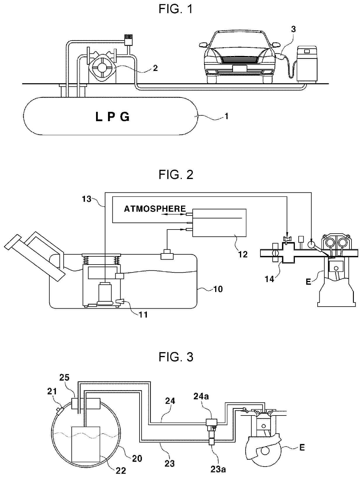
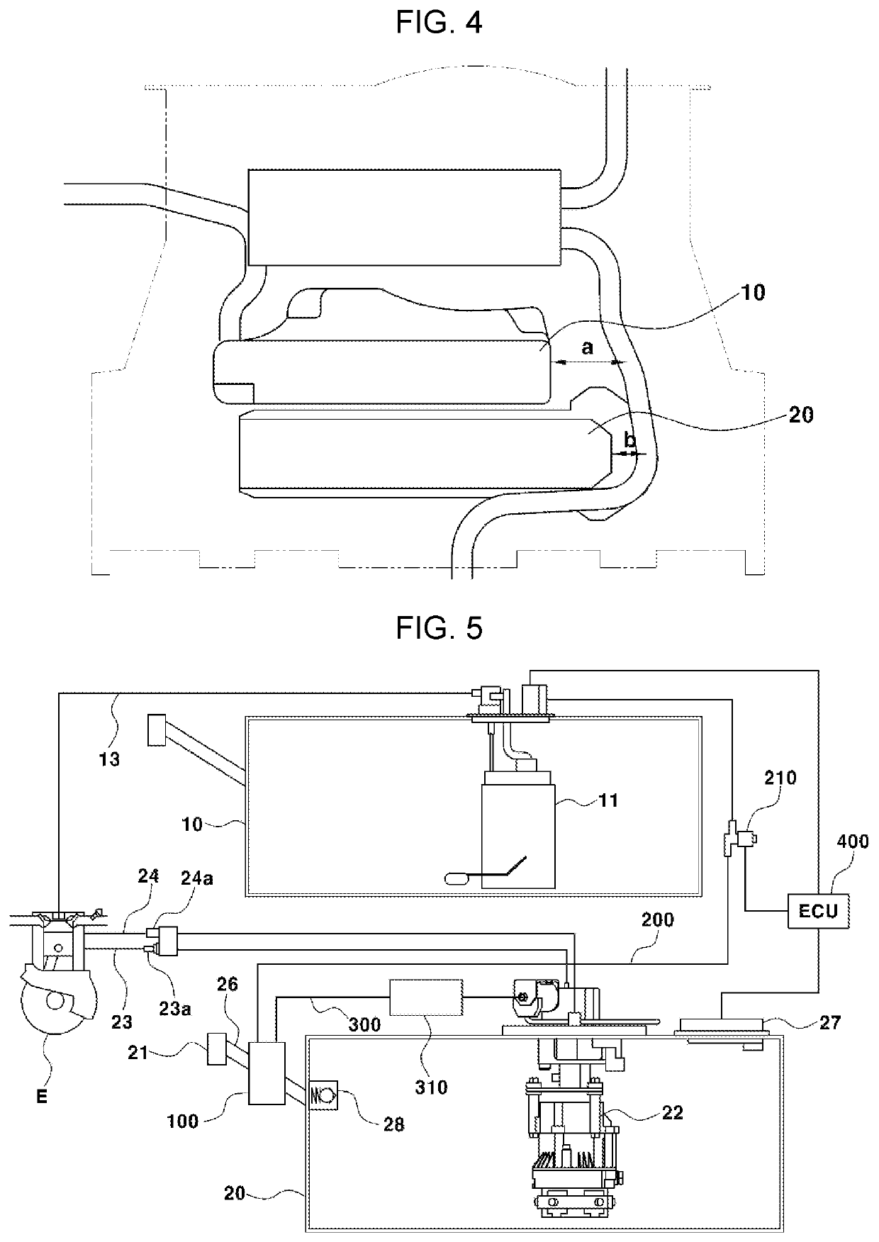
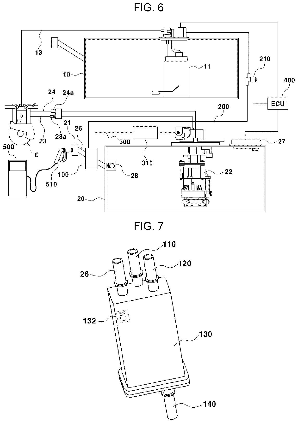
[0010]Various aspects of the present disclosure are directed to providing an apparatus and a method for charging an LPG fuel of a bi-fuel vehicle, which may install a gasoline mixing chamber in an LPG bombe, allow gasoline fuel to move to the gasoline mixing chamber as a pressure of the LPG bombe reaches a reference pressure of a charging station, and also allow LPG fuel to move to the gasoline mixing chamber so that the gasoline fuel and the LPG fuel are recirculated to an LPG bombe together to cool the inside of the LPG bombe and at the same time, decrease a vapor pressure of the LPG fuel, thereby improving the rechargeability of the LPG so that the LPG fuel may be charged even under the condition that the outside temperature rapidly increases due to the hot season.
[0021]Here, the determining of whether to enter the refueling mode maintains the state where the second valve is blocked and allows the LPG fuel to be supplied to the LPG bombe together with the gasoline fuel accommodated in the gasoline mixing chamber by use of a charging pressure of an LPG charger when it is determined as entering the refueling mode.
[0024]According to an exemplary embodiment of the present disclosure, it is possible to install the gasoline mixing chamber in the quick coupling of the LPG bombe, allow the gasoline fuel to move to the gasoline mixing chamber as the pressure of the LPG bombe reaches the reference pressure of the charging station, and also allow the LPG fuel to move to the gasoline mixing chamber so that the gasoline fuel and the LPG fuel are recirculated to the LPG bombe together, decreasing the internal pressure of the LPG bombe using the mixing of the gasoline fuel.
[0025]Therefore, according to an exemplary embodiment of the present disclosure, it is possible to cool the inside of the LPG bombe and decrease the vapor pressure of the LPG fuel, and eventually, improve the rechargeability of LPG, charging the LPG fuel even under the condition that the outside temperature rapidly increases due to the hot season.
[0026]Furthermore, according to an exemplary embodiment of the present disclosure, it is possible to allow the gasoline fuel to flow into the LPG bombe together with the LPG fuel by using the charging pressure of the LPG charging gun in the state where the gasoline is accommodated in the gasoline mixing chamber to limit the driving of the LPI pump configured for moving the LPG fuel to the gasoline mixing chamber, suppressing the use of the unnecessary energy.

Problems solved by technology

In other words, because it is difficult to accurately control the fuel amount actually supplied to the engine due to a phenomenon in which a part of the LPG fuel supplied to the engine is vaporized by high temperature (vapor lock phenomenon), a system for supplying the LPG fuel supplied to the engine in a sufficient amount greater than the amount required for combustion and returning the remaining unburned fuel to the LPG bombe is applied in consideration of the above.
At the present time, there is a problem in that when the internal temperature and pressure of the LPG bombe increase as the unburned fuel (a state where the temperature is increased by a high-temperature engine) is returned to the LPG bombe after being supplied to the engine, it is not possible to recharge the LPG fuel.
In other words, there is a problem in that when the internal temperature and pressure of the LPG bombe increase above a pressure for charging the LPG fuel in the LPG bombe by the high-temperature LPG fuel returned from the engine, it is not possible to recharge the LPG fuel from the charging gun to the LPG bombe.
Furthermore, there is a problem in that because the pressure in the LPG bombe is higher than the LPG charging pressure under the condition that the outside temperature rapidly increases due to the hot season, it is not possible to charge the LPG fuel more.

Method used


Image

  • Apparatus and method for charging LPG fuel of bi-fuel vehicle
  • Apparatus and method for charging LPG fuel of bi-fuel vehicle
  • Apparatus and method for charging LPG fuel of bi-fuel vehicle

Examples


Embodiment Construction

[0042]Reference will now be made in detail to various embodiments of the present disclosure(s), examples of which are illustrated in the accompanying drawings and described below. While the present disclosure(s) will be described in conjunction with exemplary embodiments of the present disclosure, it will be understood that the present description is not intended to limit the present disclosure(s) to those exemplary embodiments of the present disclosure. On the other hand, the present disclosure(s) is / are intended to cover not only the exemplary embodiments of the present disclosure, but also various alternatives, modifications, equivalents and other embodiments, which may be included within the spirit and scope of the present disclosure as defined by the appended claims.

[0043]Hereinafter, exemplary embodiments of the present disclosure will be described in detail with reference to the accompanying drawings.

[0044]Advantages and features of the present disclosure and a method for ach...


PUM


Abstract

An apparatus of charging Liquefied Petroleum Gas (LPG) fuel of a bi-fuel vehicle includes: a gasoline mixing chamber mounted on an LPG bombe side, a gasoline fuel supply line connecting the gasoline mixing chamber with a fuel tank and allowing gasoline fuel to move to the gasoline mixing chamber as a first valve is open, an LPG fuel supply line connecting an LPG bombe with the gasoline mixing chamber and allowing LPG fuel to move to the gasoline mixing chamber as a second valve is open, and a control unit configured to open the first valve and control the LPG fuel to be recirculated to the LPG bombe together with the gasoline fuel by a pressure of the LPG fuel moving to the gasoline mixing chamber, as an internal pressure of the LPG bombe reaches a predetermined reference pressure.

Description

CROSS-REFERENCE TO RELATED APPLICATION[0001]The present application claims priority to Korean Patent Application No. 10-2021-0036440 filed on Mar. 22, 2021, the entire contents of which is incorporated herein for all purposes by this reference.BACKGROUND OF INVENTIONField of the Present Disclosure[0002]The present disclosure relates to an apparatus and a method for charging Liquefied Petroleum Gas (LPG) fuel for a bi-fuel vehicle, and more specifically, to an apparatus and a method for charging LPG fuel for a bi-fuel vehicle, which may separately install a gasoline mixing chamber in an LPG bombe and allow gasoline to move to the gasoline mixing chamber so that gasoline fuel and the LPG fuel are selectively recirculated to the LPG bombe together to cool the inside of the LPG bombe and decrease the vapor pressure of the LPG fuel, improving the rechargeability of the LPG.Description of Related Art[0003]Currently, a fuel supply system for returning a part of the LPG fuel supplied to an ...

Claims


Application Information

Patent Timeline
Patent Type & Authority Applications(United States)
IPC IPC(8): F02D19/06F02D19/08
CPCF02D19/0647F02D19/0681F02D19/08F02D19/0605F02D19/0665F02D19/0684F02D19/0694F02D41/0025F02D19/0673F02M37/0052
Inventor KIM, CHANG HANJI, SUNG HWANCHOI, SEUNG HOONLIM, JUN SIK
Owner HYUNDAI MOTOR CO LTD
Why Eureka
Try Eureka