Frequency-shift determination

a technology of frequency shift and determination, applied in the field of frequency shift determination, can solve the problems of cross-correlation-based decoding, distorted frequency and phase of received signals, and poor performance of cross-correlation-based decoding in such circumstances

Pending Publication Date: 2022-09-29
SONITOR TECH
View PDF0 Cites 0 Cited by
  • Summary
  • Abstract
  • Description
  • Claims
  • Application Information

AI Technical Summary

Benefits of technology

[0029]Thus it will be seen that, in accordance with the invention, the received signal is deconvolved using templates of the transmitted signal under a number of different frequency-shift assumptions, and the frequency shift that gives rise to a peak signal-to-noise measure in the resulting impulse response function is identified. The identified frequency shift may provide a best estimate of a motion-induced Doppler shift experienced by the signal. This idea of using a signal-to-noise measure to determine a frequency shift is based on an insight that a time-domain representation of an impulse response function generated by deconvolving the received signal with a template that is not frequency-matched with the received signal will typically contain large noise peaks (which may be periodic) that do not arise from received reflections of the transmitted signal. By contrast, a frequency-matched template will typically yield high peaks only for true signal paths, with only much lower level peaks arising from noise factors. Thus, a signal-to-noise measure can effectively discriminate between a frequency-matched template and non-frequency-matched templates, in such a deconvolution operation.
[0061]However, in some embodiments, some or all of the processing system may be remote from the receiver—e.g. located on one or more servers. This may be advantageous in reducing the processing requirement on a mobile receiver unit, which can reduce its cost and power consumption, even after accounting for the need to transmit data from the mobile receiver unit (e.g., by radio). The processing system may be split across multiple processors or multiple locations, or both. The mobile receiver unit may be configured to transmit the received signal, or information derived therefrom, to a remote processing unit. The mobile receiver unit may comprise a wired or wireless transmitter, such as a radio transmitter, for transmitting information relating to the received signal.

Problems solved by technology

Because the mobile device may be in motion as the signals are received, the frequency and phase of the received signals may be distorted due to Doppler shift.
A cross-correlation-based decoding can perform poorly in such circumstances.
However, a signal modulated with continuous-phase frequency-shift-keying (CP-FSK) has a much more broadband frequency spectrum than a QPSK-modulated CCK signal, and gives rise to much less reliable frequency-shift estimates when attempting to cross-correlate against templates in the frequency domain.

Method used


Image

  • Frequency-shift determination
  • Frequency-shift determination
  • Frequency-shift determination

Examples


Embodiment Construction

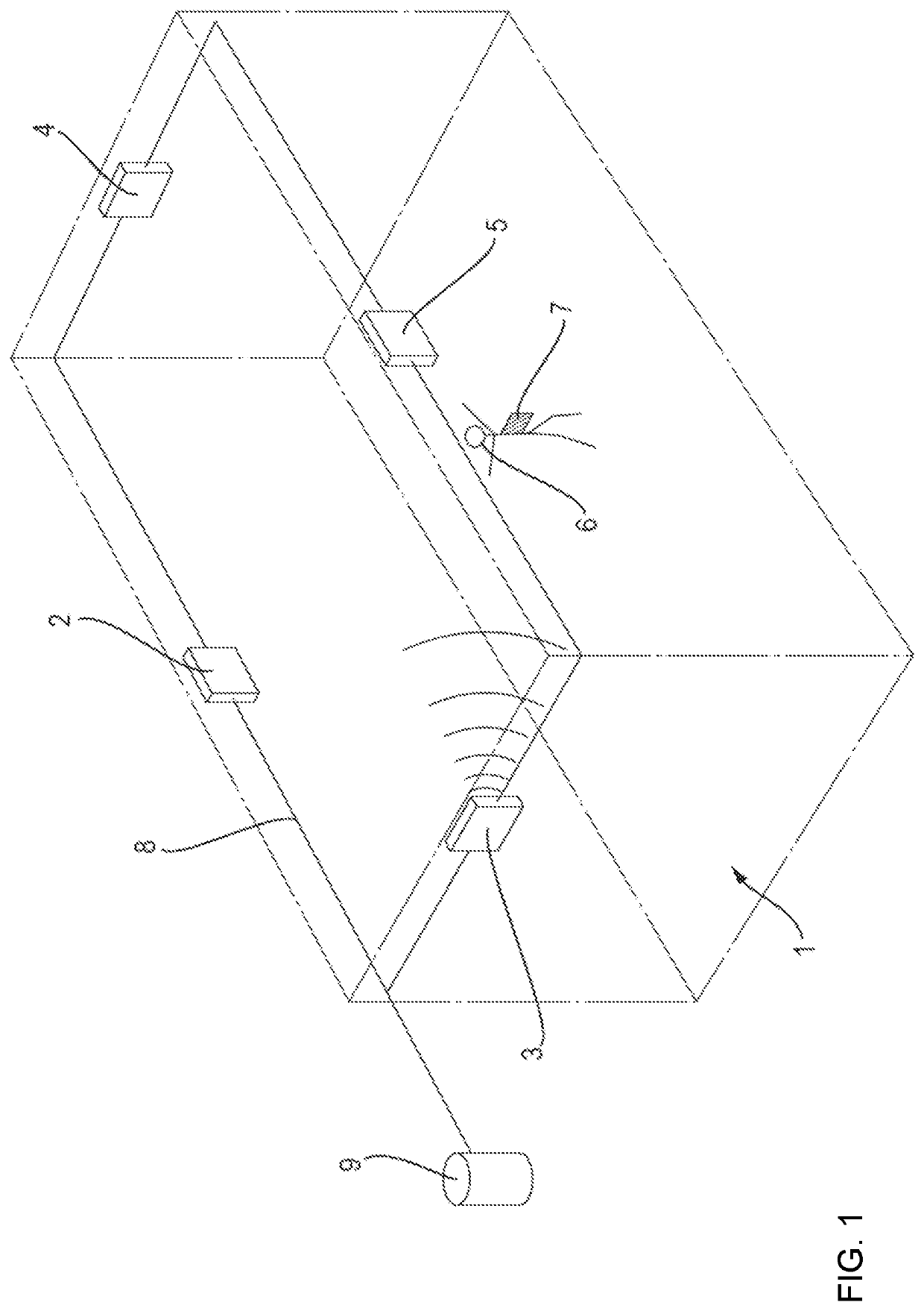
[0073]FIG. 1 shows part of a positioning system that may be used in, for example, a shopping mall in order to determine the locations of shoppers within the shopping mall. Of course, this is just one example environment, and the positioning system could also be used in warehouses, hospitals, domestic homes, vehicles, etc.

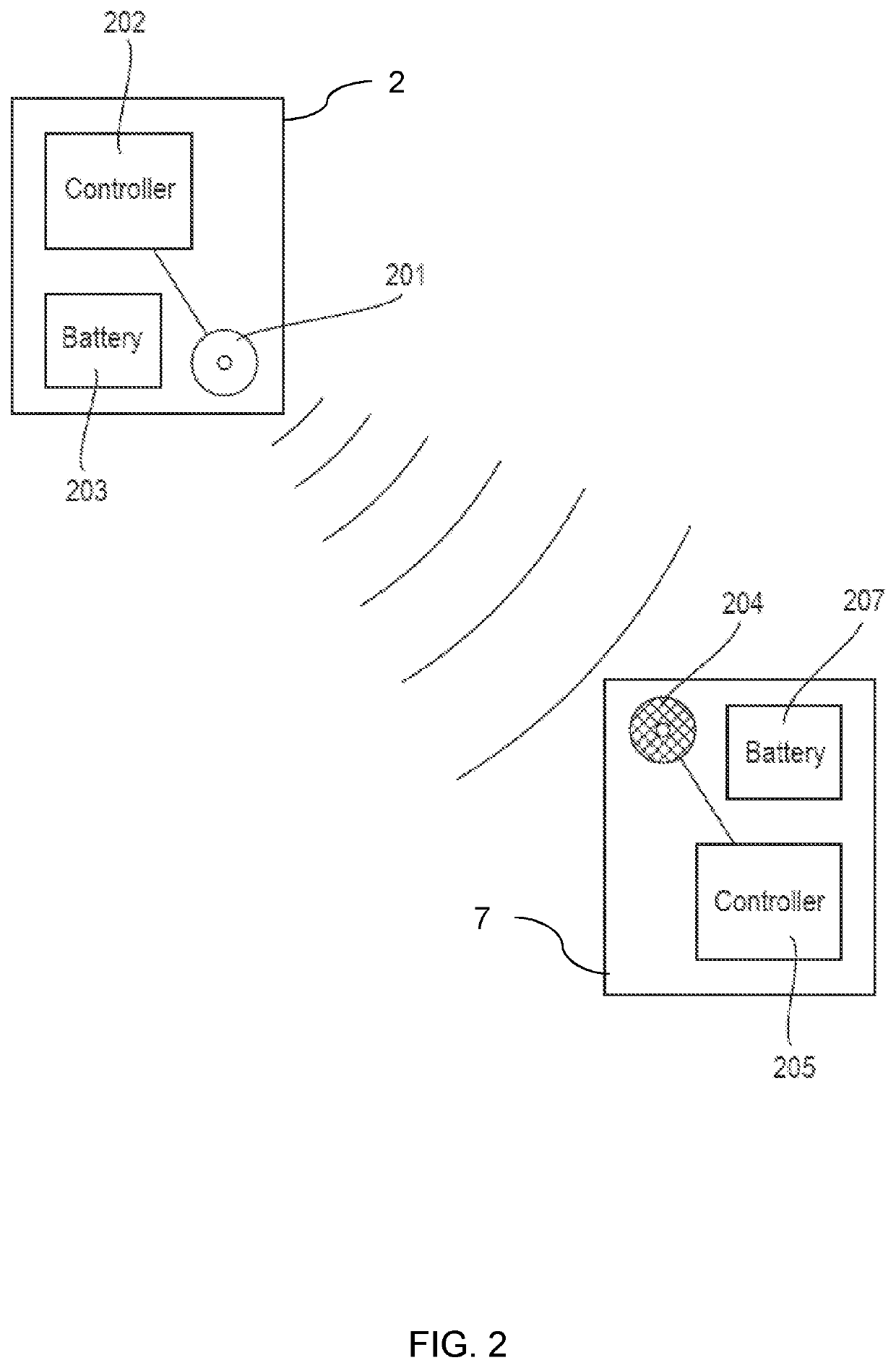
[0074]FIG. 1 shows a room 1, to the walls of which are affixed four static transmitter units 2, 3, 4, 5. A person 6 in the room is carrying a mobile receiver unit 7. A network cable 8 connects each transmitter unit 2, 3, 4, 5 to a server 9, which is typically located in another room or in another building. These components cooperate to provide a positioning system, capable of estimating the three-dimensional location of the mobile receiver unit 7 within the room 1. In practice, the system may have further similar transmitter units, installed throughout a building or series of rooms, and a plurality of similar mobile receiver units attached to, or incorporated into, ...


PUM


Abstract

A receiving apparatus (7) that can estimate a motion-induced frequency shift in a received signal comprises a processing system (205) and a receiver (204) configured to receive a signal comprising one or more instances of a transmitted signal. The processing system (205) is configured to generate data representative of a plurality of impulse response functions by deconvolving the received signal with each of a plurality of templates representative of the transmitted signal shifted in frequency by a different respective frequency shift. The processing system (205) is further configured to evaluate a signal-to-noise measure for each of the plurality of impulse response functions, and to identify an impulse response function of the plurality of impulse response functions for which the signal-to-noise measure satisfies a peak criterion.

Description

BACKGROUND OF THE INVENTION[0001]This invention relates to apparatus and methods for determining a frequency shift in a signal.[0002]It is known to use signals, such as ultrasonic signals, to track the position of mobile units, or tags, in two or three dimensions, by transmitting signals from a plurality of transmitter units, which may be fixed to the walls or ceilings of a building. The signals encode identifiers of the respective transmitters units. These signals are received by the mobile receiver units, which may be attached to objects such as people or equipment. If the positions of the static transmitter units are known, the times of arrival of signals from the transmitter units at a mobile unit can be used to estimate the position of the mobile unit in the environment, based on geometric principles such as the intersection of circles or spheres.[0003]In WO 2019 / 038542 the present applicant disclosed real-time locating systems (RTLS) in which a plurality of static transmitter ...

Claims


Application Information

Patent Timeline
Patent Type & Authority Applications(United States)
IPC IPC(8): G01S5/30G01S11/14
CPCG01S5/30G01S11/14G01S5/18
Inventor BOOIJ, WILFRED EDWIN
Owner SONITOR TECH
Why Eureka
Try Eureka