Surface coating cutting tool

a cutting tool and surface coating technology, applied in the direction of manufacturing tools, turning machine accessories, superimposed coating process, etc., can solve the problems of reducing the life of the tool, and achieve the effects of excellent high-temperature strength, excellent chipping resistance, peeling resistance, and wear resistan

Active Publication Date: 2017-03-30
MITSUBISHI MATERIALS CORP
View PDF1 Cites 0 Cited by
  • Summary
  • Abstract
  • Description
  • Claims
  • Application Information

AI Technical Summary

Benefits of technology

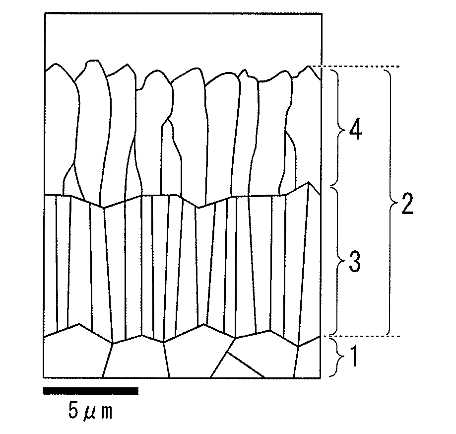
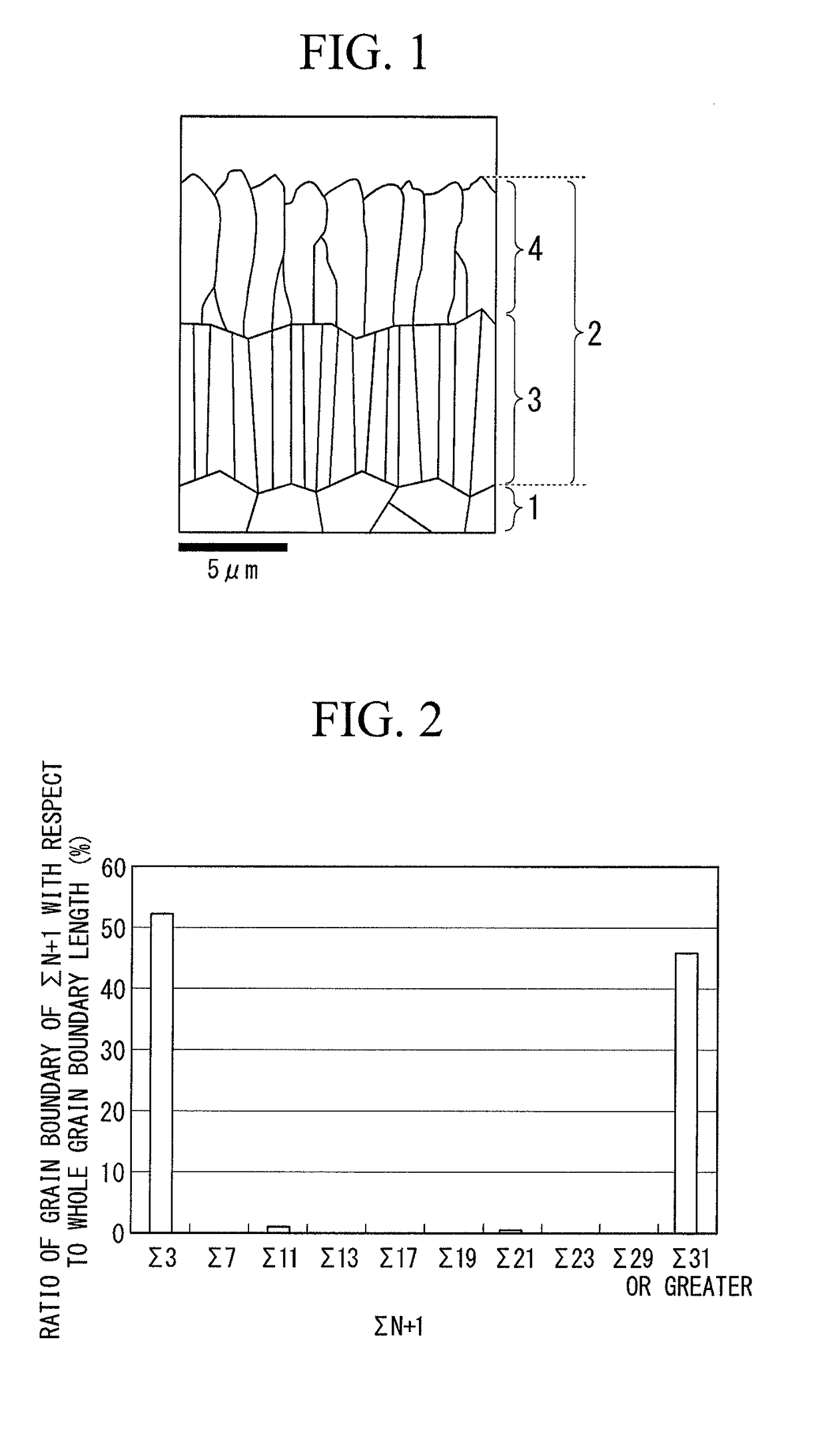
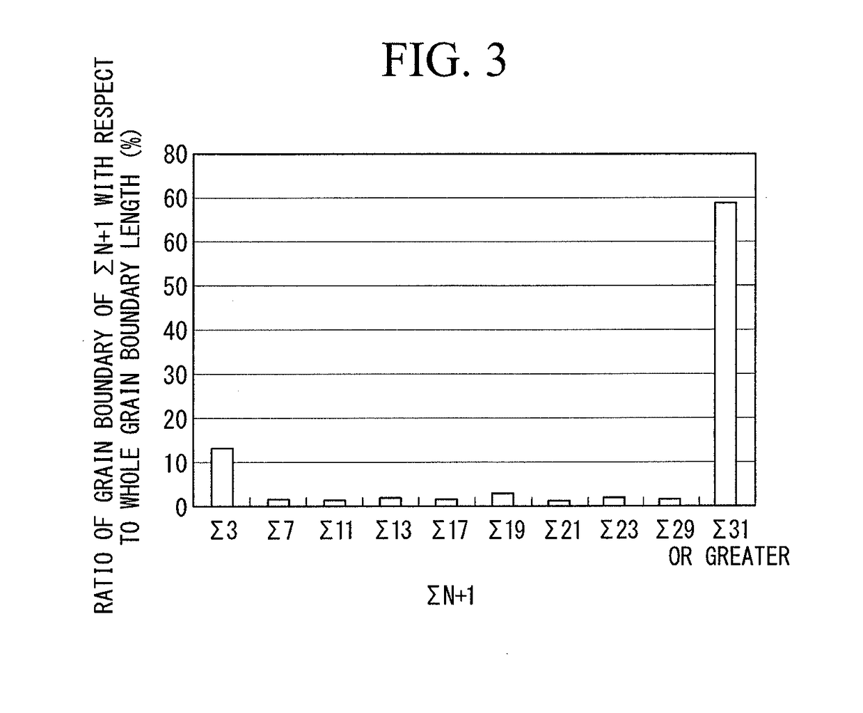
[0021]According to the coated tool of the invention, the hard coating layer has a lower layer that is formed on the surface of the tool body and an upper layer that is formed on the lower layer; (a) the lower layer is made of a Ti compound layer, which has an average total layer thickness of 3 to 20 μm, and is composed of two or more of a TiC layer, a TiN layer, a TiCN layer, a TiCO layer, and a TiCNO layer, the Ti compound layer including at least one TiCN layer; and (b) the upper layer is made of an Al2O3 layer, which has an average layer thickness of 1 to 30 μm and has an α-type crystal structure in a chemically deposited state. In addition, in the invention, in a case where a coincidence grain boundary distribution, regarding the individual crystal grains, constituting the Al2O3 layer is obtained using a field-emission-type scanning electron microscope and an electron beam backward scattering diffraction device, a highest peak is present in Σ3 in the range of Σ3 to Σ29, a distribution ratio of Σ3 occupies 35 to 70%, and a distribution ratio of Σ31 or more occupies 25 to 60% in regard to the Al2O3 crystal grains. The coated tools of the invention have such a characteristic configuration, and thus characteristic effects such as excellent chipping resistance, defect resistance, peeling resistance, and wear resistance are obtained.
[0022]Therefore, according to the coated tool of the invention, even in a case where cutting work of various steels, cast irons, and the like is performed at a high speed under high-speed heavy cutting conditions or high-speed intermittent cutting conditions in which a high mechanical impact load is exerted a cutting edge, excellent high-temperature strength, high-temperature toughness, and high-temperature hardness are exhibited, and excellent wear resistance is exhibited over a long-term of usage with no occurrence of abnormal damage such as chipping, defect, and peeling.

Problems solved by technology

However, in a case where the coated tool is used in high-speed intermittent cutting, peeling or chipping of the coating layer easily occurs, and there is a problem in that the tool life is reduced.

Method used


Image

  • Surface coating cutting tool
  • Surface coating cutting tool
  • Surface coating cutting tool

Examples


examples

[0077]A WC powder, a TiC powder, a ZrC powder, a TaC powder, a NbC powder, a Cr3C2 powder, a TiN powder, and a Co powder having an average grain size of 1 to 3 μm were prepared as raw material powders. These raw material powders were blended according to a blending composition shown in Table 1. Wax was added and mixed therewith using a ball mill for 24 hours in acetone and dried under reduced pressure. Thereafter, the resulting material was press-formed into a green compact having a predetermined shape at a pressure of 98 MPa, and this green compact was vacuum-sintered by being kept at a predetermined temperature of 1370° C. to 1470° C. for 1 hour in a vacuum of 5 Pa. After sintering, tool bodies A to E made of a WC-based cemented carbide and having an insert shape defined in ISO-CNMG120408 were produced.

[0078]A TiCN powder (TiC / TiN=50 / 50 in terms of mass ratio), a ZrC powder, a TaC powder, a NbC powder, a Mo2C powder, a WC powder, a Co powder, and a Ni powder having an average grai...


PUM

PropertyMeasurementUnit
thicknessaaaaaaaaaa
thicknessaaaaaaaaaa
thicknessaaaaaaaaaa

Abstract

A surface-coated cutting tool of the invention is a surface-coated cutting tool in which a surface of a tool body is coated with a lower layer and an upper layer, in which at least one layer of the lower layer is made of a TiCN layer, the upper layer has an average layer thickness of 2 to 15 μm and is made of an Al2O3 layer having an α-type crystal structure in a chemically deposited state, and in a coincidence grain boundary distribution graph, a highest peak is present in Σ3 in the range of Σ3 to Σ29, a distribution ratio of Σ3 occupies 35 to 70% of the whole coincidence grain boundary length of Σ3 or more, and a coincidence grain boundary of Σ31 or more occupies 25 to 60% of the whole coincidence grain boundary length of Σ3 or more.

Description

CROSS-REFERENCE TO RELATED PATENT APPLICATIONS[0001]This application is a U.S. National Phase Application under 35 U.S.C. §371 of International Patent Application No. PCT / JP2015 / 063885, filed May 14, 2015, and claims the benefit of Japanese Patent Applications No. 2014-101888, filed May 16, 2014 and No. 2015-097280, filed May 12, 2015, all of which are incorporated by reference herein in their entireties. The International Application was published in Japanese on Nov. 19, 2015 as International Publication No. WO / 2015 / 174490 under PCT Article 21 (2).FIELD OF THE INVENTION[0002]The present invention relates to a surface-coated cutting tool (hereinafter, referred to as a coated tool) exhibiting excellent wear resistance over a long period of time. In this coated tool, a hard coating layer exhibits excellent peeling resistance and chipping resistance even in a case where cutting work of various steels, cast irons, and the like is performed at a high speed under intermittent cutting cond...

Claims


Application Information

Patent Timeline
Patent Type & Authority Applications(United States)
IPC IPC(8): B23B27/14C23C28/04
CPCB23B27/148C23C28/044C23C28/042B23B2222/16B23B2228/105B23B2224/28B23B2224/32B23B2224/36B23B2224/04B23B2222/28B23B27/14C23C30/005C23C16/30B23B2228/10
Inventor OKUDE, MASAKIYAMAGUCHI, KENJI
Owner MITSUBISHI MATERIALS CORP
Why Eureka
Try Eureka