Wind turbine blade tool and method for producing a wind turbine blade

Pending Publication Date: 2022-10-06
BLADE DYNAMICS LTD +1
View PDF0 Cites 0 Cited by
  • Summary
  • Abstract
  • Description
  • Claims
  • Application Information

AI Technical Summary

Benefits of technology

The present invention provides a tool and method for manufacturing a wind turbine blade that increases accuracy of positioning components and reduces manufacturing time. The tool has first and second engaging surfaces with alignment tabs that ensure correct alignment of blade components. The alignment tabs prevent movement of the blade component in a direction parallel and / or perpendicular to the longitudinal direction of the blade mold and / or in a plane parallel to the longitudinal direction of the blade mold. The tool and mold guiding parts prevent movement of the placement tool relative to the blade mold in certain directions. The technical effects of the invention include increased accuracy of positioning components, reduced manufacturing time, and improved mechanical properties of the assembled blade.

Problems solved by technology

However, it may be complicated to assemble a wind turbine blade with a flatback trailing edge.
In particular, it may be challenging to accurately position components to be bonded to the trailing edge part of the blade when the blade comprises a flatback profile.

Method used


Image

  • Wind turbine blade tool and method for producing a wind turbine blade
  • Wind turbine blade tool and method for producing a wind turbine blade
  • Wind turbine blade tool and method for producing a wind turbine blade

Examples


Embodiment Construction

[0054]In the following figure description, the same reference numbers refer to the same elements and may thus not be described in relation to all figures.

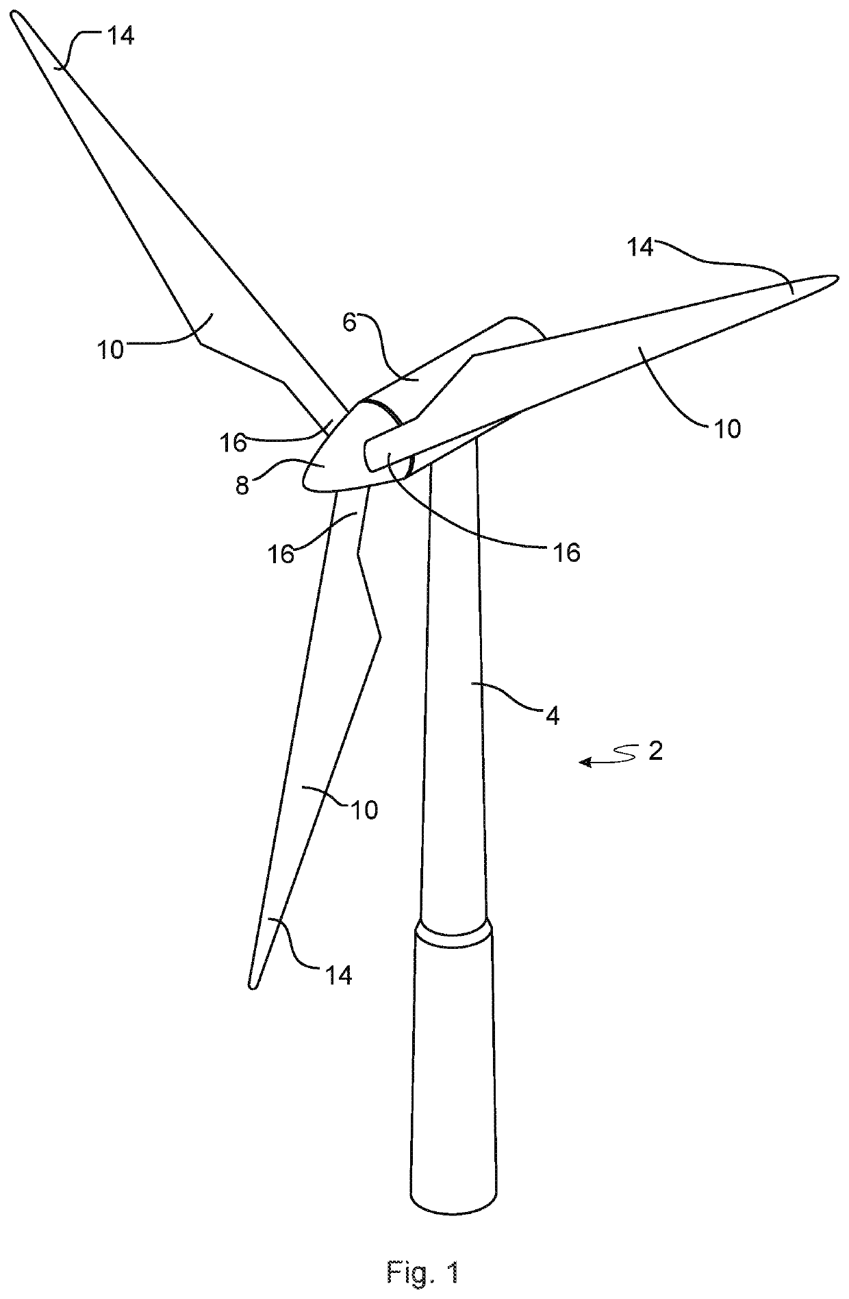
[0055]FIG. 1 illustrates a conventional modern upwind wind turbine 2 according to the so-called “Danish concept” with a tower 4, a nacelle 6 and a rotor with a substantially horizontal rotor shaft. The rotor includes a hub 8 and three blades 10 extending radially from the hub 8, each having a blade root 16 nearest the hub and a blade tip 14 furthest from the hub 8.

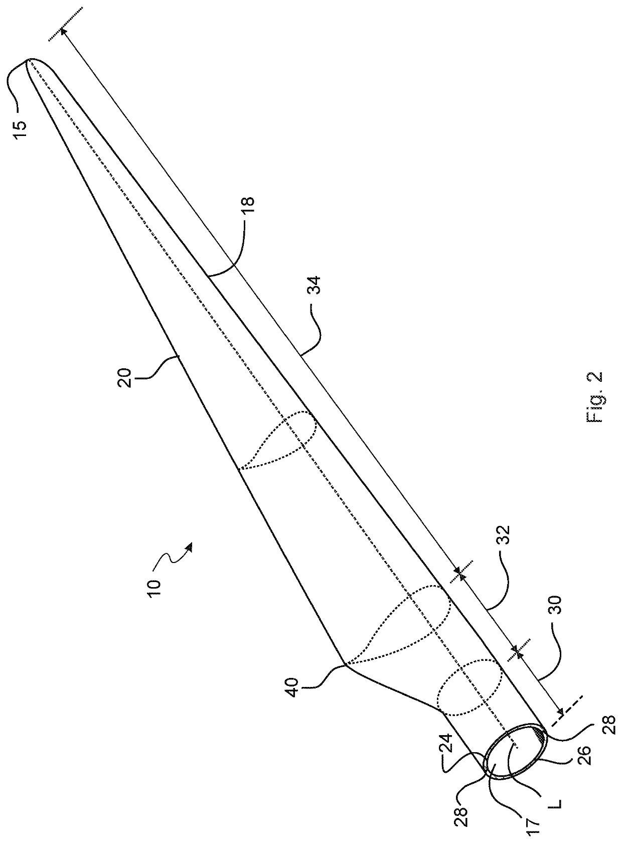
[0056]FIG. 2 shows a schematic view of an exemplary wind turbine blade 10. The wind turbine blade 10 has the shape of a conventional wind turbine blade with a root end 17 and a tip end 15 and comprises a root region 30 closest to the hub, a profiled or an airfoil region 34 furthest away from the hub and a transition region 32 between the root region 30 and the airfoil region 34. The blade 10 comprises a leading edge 18 facing the direction of rotation of the blade 10, whe...


PUM

PropertyMeasurementUnit
Pressureaaaaaaaaaa
Shapeaaaaaaaaaa
Areaaaaaaaaaaa

Abstract

Disclosed is a blade mould system for manufacturing of a wind turbine blade shell, the blade mould system comprising a blade mould having a moulding surface for defining an outer shape of a blade shell part, the blade shell part having an outer surface facing the moulding surface and an inner surface facing away from the moulding surface, and a first placement tool being positioned at a first placement tool position relative to the blade mould, the placement tool being adaptable between a first configuration and a second configuration. The first placement tool being configured to engage with a blade component being in a primary component position and position the blade component at a secondary component position relative to the moulding surface by the first placement tool attaining the second configuration, wherein the blade component is configured to be attached to the blade shell part in the secondary component position, wherein the first placement tool comprises a first movable part and a first stationary part.

Description

[0001]The present disclosure relates to wind turbine blades and manufacture of wind turbine blades. More specifically, the present disclosure pertains to the field of joining of parts of a wind turbine blade, such as joining of component, such as webs, glue flanges, etc.BACKGROUND[0002]Wind turbine blades of fibre-reinforced polymer and in particular the aerodynamic shells of wind turbine blades are usually manufactured in moulds, where the pressure side and the suction side of the blade are manufactured separately by arranging glass fibre mats and / or other fibre-reinforcement material, such as carbon fibre, in each of the two moulds. Afterwards, one of the two halves is turned upside down and positioned on top of the other of the two halves, and the two halves are adhered together. The blade parts may be positioned on top of each other by turning and repositioning the complete half mould.[0003]A wind turbine blade and / or components of the wind turbine blade, such as webs and / or she...

Claims


Application Information

Patent Timeline
IPC IPC(8): B29D99/00
CPCB29D99/0028F03D1/0675B29C70/541B29L2031/085B29C65/7847B29C65/483B29C66/1122B29C66/301B29C66/54B29C66/532B29C66/534B29C65/7835B29C65/7876B29C66/7212B29C66/71Y02P70/50B29C33/12B29K2309/08B29K2307/04B29K2063/00B29K2067/00F05B2230/21
Inventor MUKHERJEE, MANISHLUND-LAVERICK, MICHAEL
Owner BLADE DYNAMICS LTD
Why Eureka
Try Eureka