System for supplying hydrogen gas to engine

a hydrogen gas and engine technology, applied in the direction of electrical control, speed sensing governor, container discharging method, etc., can solve the problems of large number of cylinders to be loaded, large amount of hydrogen required, unrealistic, etc., and achieve the effect of increasing the degree of freedom of installation

Pending Publication Date: 2022-10-13
HIT RES INST CORP
View PDF31 Cites 0 Cited by
  • Summary
  • Abstract
  • Description
  • Claims
  • Application Information

AI Technical Summary

Benefits of technology

[0017]According to the hydrogen gas supply system of the present invention, without selecting a hydrogen gas producer for producing a large amount of hydrogen per unit time, even if the required amount of hydrogen to be added increases according to a fluctuation in the load on the engine, the increase can be covered with the hydrogen from the hydrogen absorbing alloy cylinder. Thus, a relatively small device can be used as the hydrogen gas producer, and the degree of freedom of installation is increased.
[0018]According to the hydrogen gas supply system according to the second aspect of the present invention, the hydrogen gas from the hydrogen gas producer is always supplied to the hydrogen absorbing alloy cylinder, and thereby the hydrogen absorbing alloy cylinder serves as a storage, and as in the first aspect of the present invention, a relatively small device can be used as the hydrogen gas producer, and the degree of freedom of installation is increased.
[0019]According to the third and fourth aspects of the present invention, even when hydrogen gas is supplied to the gas fuel line in the system, it is possible to continuously supply hydrogen gas for a long period of time.

Problems solved by technology

However, a vessel or the like uses an engine of an extremely large displacement and continuously operates such an engine for a long period of time, which requires a large amount of hydrogen.
In some existing vessels or the like, such an electrolysis apparatus cannot be installed in their limited space such as an engine room.
For the operation of an engine for a long period of time such as one week or one month, however, a large number of cylinders must be loaded, which is not realistic.

Method used


Image

  • System for supplying hydrogen gas to engine
  • System for supplying hydrogen gas to engine
  • System for supplying hydrogen gas to engine

Examples


Embodiment Construction

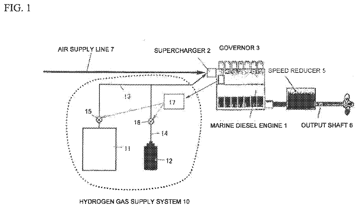
[0031]Hereinafter, embodiments of the present invention will be described with reference to the accompanying drawings. FIG. 1 shows an example in which a hydrogen gas supply system according to the first aspect of the present invention is applied to a marine diesel engine. The marine diesel engine 1 includes a supercharger 2, a governor 3 to maintain the engine rotation speed within a certain range even if the load fluctuates, a speed reducer 5 (not equipped in a low-speed engine) for decreasing the rotation of the engine, and a propeller shaft 6 (output shaft).

[0032]An air supply line (piping) 7 for taking in outside air into the engine has, at one end, the supercharger 2. To the air supply line 7 including the supercharger 2, a trace amount of hydrogen gas is sent via the hydrogen gas supply system 10. (In an engine having no supercharger, hydrogen is put into an air filter.)

[0033]The hydrogen gas supply system 10 includes a hydrogen gas producer 11 for electrolyzing pure water to...


PUM


Abstract

A system for supplying hydrogen gas to an engine is disclosed. The system includes a main line configured to send hydrogen gas produced in a hydrogen gas producer by electrolysis to a supply line; a sub-line configured to send hydrogen gas from a hydrogen absorbing alloy cylinder to the main line, a governor configured to maintain an engine rotation speed within certain range; and a control device. The governor sends a signal corresponding to the engine rotation speed to the control device. A pressure regulating valve is disposed in the sub-line to be downstream with respect to the hydrogen absorbing alloy cylinder to regulate a supply amount of added hydrogen. An opening degree of the valve is adjusted based on a signal from the control device corresponding to the opening degree of the valve for supplying the added hydrogen with an amount according to a load state of the engine.

Description

CROSS-REFERENCE TO RELATED APPLICATIONS[0001]This application is the U.S. National Phase of International Application No. PCT / JP2020 / 040311, filed Oct. 27, 2020. This application claims priority to Japanese Patent Application No. 2019-196841 filed Oct. 30, 2019, and Japanese Patent Application No. 2020-115462 filed Jul. 3, 2020. The entire contents of those applications are incorporated by reference herein in their entireties.TECHNICAL FIELD[0002]The present invention relates to a system for supplying hydrogen gas to air supply or to a gas fuel supply line, and relates to a system that enables long-term supply of hydrogen gas.BACKGROUND ART[0003]Japanese Patent No. 6328186 proposes an addition of a trace amount (0.01 to 0.1 vol %) of hydrogen to air supply as a method for efficient combustion of a polymer liquid fuel such as gasoline, diesel, or heavy oil in an engine.[0004]In the method, when the fuel is ignited, the hydrogen gas in the air supply is also ignited, and the combustio...

Claims


Application Information

Patent Timeline
Patent Type & Authority Applications(United States)
IPC IPC(8): F02D19/02F02D31/00F02M21/02
CPCF02D19/022F02D31/007F02M21/0206F02M21/0239F02D2200/101Y02T10/30Y02E60/32Y02P90/45F17C7/00F17C11/00F02D31/001F02D41/0027C01B3/0031
Inventor ITO, MASANORIJABANA, YOSHIHIROHARADA, TSUTOMU
Owner HIT RES INST CORP
Why Eureka
Try Eureka