
Method Of Identifying An Object Signature In An Environment And System For Identifying An Object Signature In An Environment

a technology of object signature and environment, applied in the field of infrared observation systems, can solve the problems of complex hyperspectral sensors suitable for capturing infrared bands, high cost, and difficulty in aircraft or other platforms to us

Pending Publication Date: 2022-10-13
AIRBUS DEFENCE & SPACE
View PDF0 Cites 0 Cited by
  • Summary
  • Abstract
  • Description
  • Claims
  • Application Information

AI Technical Summary

Benefits of technology

The invention provides a method and system for identifying the signature of an object using infrared imaging. The method involves detecting only three specific wavelength bands of infrared radiation, instead of the entire spectra, to reduce data processing requirements and improve object recognition. This approach also improves human-machine interaction by generating a colored image of the detected signals. The system has applications in missile warnings, object tracking, and situational awareness, and can provide valuable information to improve the performance of current missile approach warning systems. The processing of the detection, determination, and classification steps is simplified by using only three wavelength bands, resulting in a low data stream and improved processing efficiency. The use of spectral information also enables the discrimination of sources and avoidance of false alarms in missile warnings, and the tracking of objects in tracker applications.

Problems solved by technology

Hyperspectral sensors suitable to capture infrared bands are complex, expensive and may be difficult to use in aircraft or other platforms due to environmental constraints, especially in military aircraft.

Method used


Image

  • Method Of Identifying An Object Signature In An Environment And System For Identifying An Object Signature In An Environment
  • Method Of Identifying An Object Signature In An Environment And System For Identifying An Object Signature In An Environment
  • Method Of Identifying An Object Signature In An Environment And System For Identifying An Object Signature In An Environment

Examples


Embodiment Construction

[0054]The representations and illustrations in the drawings are schematic and not to scale. A better understanding of the method and system described above may be obtained through a review of the illustrations accompanying this application together with a review of the detailed description that follows.

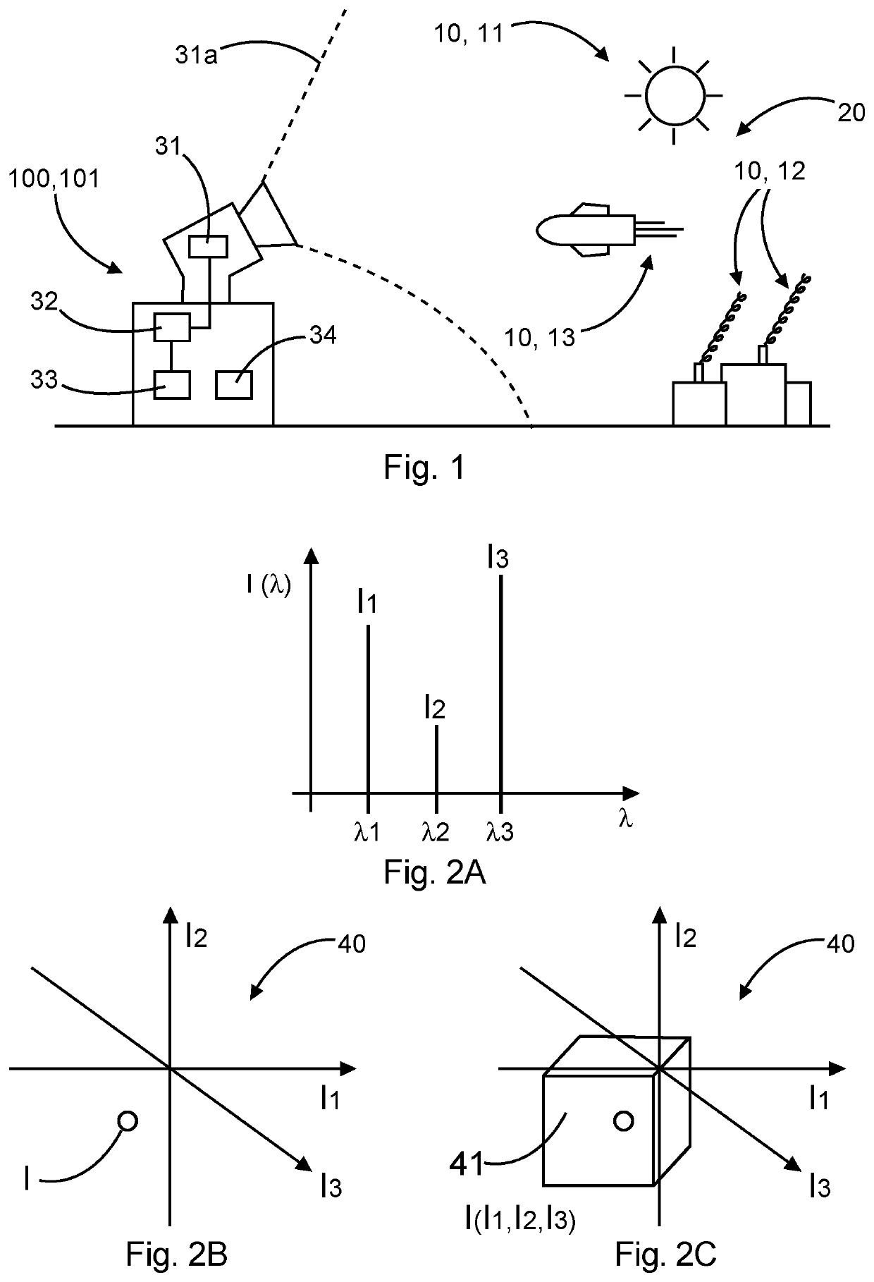
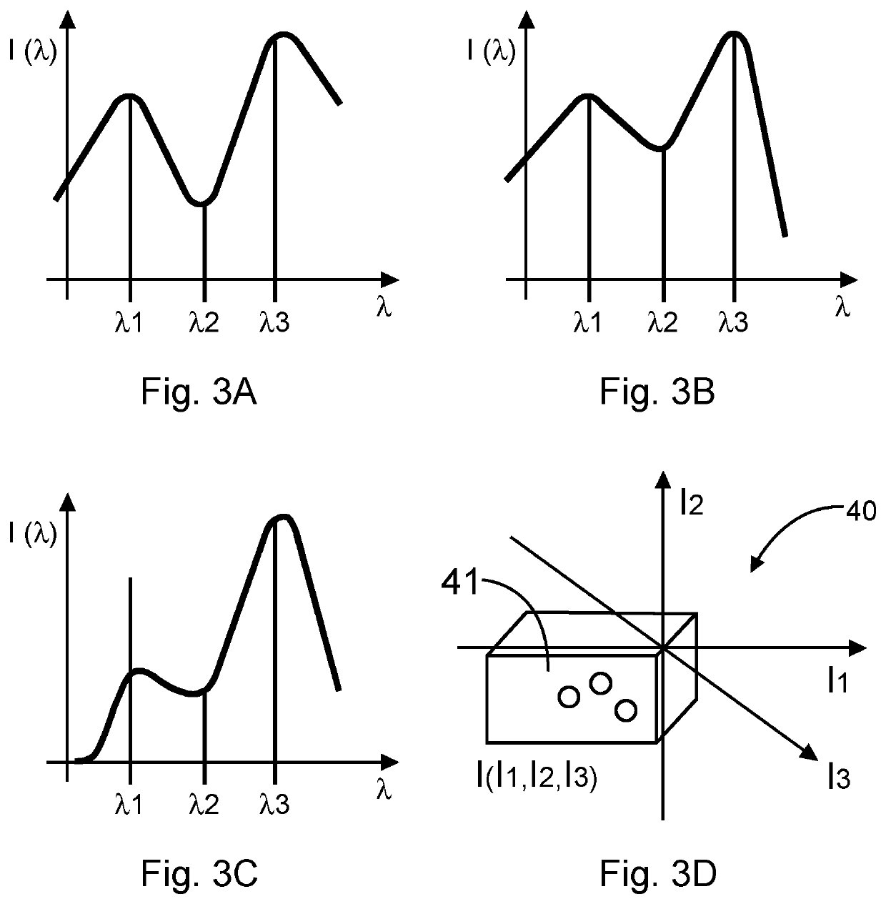
[0055]FIG. 1 shows a system 100, for example a stationary missile warning system 101, for identifying an object signature 10 in an environment 20. The system 100 comprises a detection unit 31 configured to acquire infrared information from the environment 20 in order to obtain an infrared wavelength spectrum associated with the environment 20. Infrared information from the environment 20 may be acquired from within a field of view 31a covered by the detection unit 31. The detection unit 31 may be an infrared sensor. The system further comprises a filtering unit 32 configured to select three wavelength bands λ1, λ2, λ3 of the infrared wavelength spectrum and a processing unit 33 is con...


PUM


Abstract

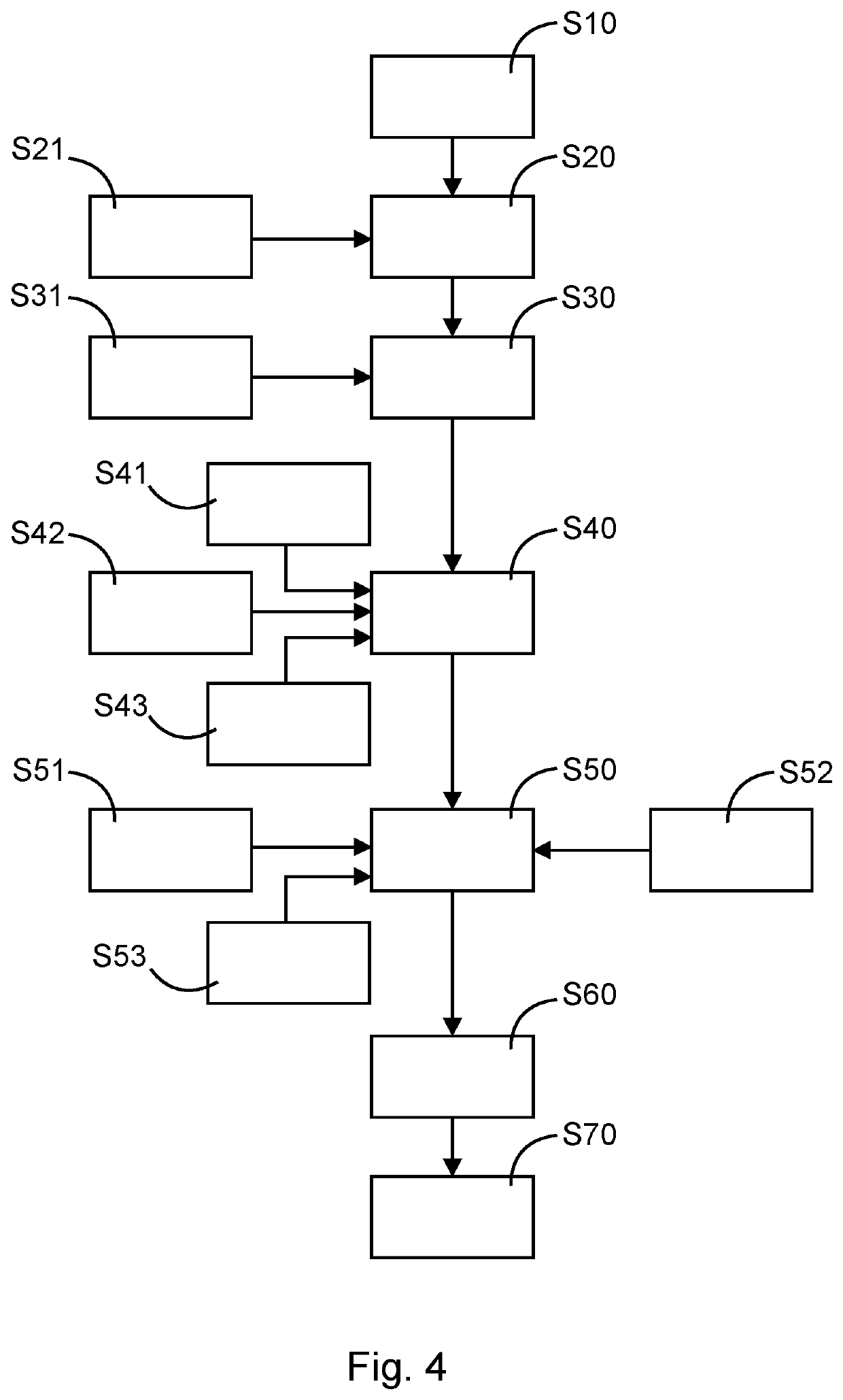
A method of identifying an object signature in an environment includes acquiring infrared information from the environment using a detection unit in order to obtain an infrared wavelength spectrum associated with the environment. The method further includes selecting three wavelength bands of the infrared wavelength spectrum using a filtering unit and detecting a presence of the three wavelength bands of the infrared wavelength spectrum in the environment by filtering the selected three wavelength bands using the filtering unit. The method further includes determining an intensity indicator for the three selected wavelength bands using a processing unit and classifying the object signature using the processing unit based on the determined intensity indicator in order to identify the object signature.

Description

FIELD OF THE INVENTION[0001]The invention relates to infrared observation systems. In particular, the invention relates to a method of identifying an object signature in an environment as well as to a system for identifying an object signature in an environment.BACKGROUND OF THE INVENTION[0002]Object signature identification is an important aspect, in particular for military defense systems. Object signature identification can be used to recognize and protect aircraft from air-to-air (AA) or surface-to-air (SA) missiles threats, including man-portable air defense systems (MANPADS). Such an identification requires extended capabilities to analyze the spectral domain. This also includes the analysis of the infrared spectrum, typically of the short-wave infrared spectrum (SWIR), the mid-wave infrared spectrum (MWIR) and the long-wave infrared spectrum (LWIR). Hyperspectral sensors suitable to capture infrared bands are complex, expensive and may be difficult to use in aircraft or other...

Claims


Application Information

Patent Timeline
Patent Type & Authority Applications(United States)
IPC IPC(8): F41H11/02F41J2/02F41G7/22G01S7/495
CPCF41H11/02F41J2/02F41G7/224G01S7/495G01N21/3504G01N2021/3531G01N2021/3148G01N2021/1795
Inventor ALBERTONI, ALESSANDRORIEDEL, KARSTENWITTMANN, DAVID
Owner AIRBUS DEFENCE & SPACE
Learn More