Method for locating a leak in a water supply network

a water supply network and leak detection technology, applied in the direction of fluid tightness measurement, instrumentation, service pipe system, etc., can solve the problems of water loss in water grids, noise generation, and difficulty in determining the exact location of leaks

Pending Publication Date: 2022-10-13
KAMSTRUP
View PDF0 Cites 0 Cited by
  • Summary
  • Abstract
  • Description
  • Claims
  • Application Information

AI Technical Summary

Problems solved by technology

The most common water loses in water grids are caused by leaks in the pipe networks.
When water exits a pressurized pipe through a leak, noise is generated.
This acoustic leak detection works very well in practice, however, it is difficult to determine the exact location of the leak.
This is time consuming, expensive and obstructing traffic.

Method used


Image

  • Method for locating a leak in a water supply network
  • Method for locating a leak in a water supply network

Examples


Embodiment Construction

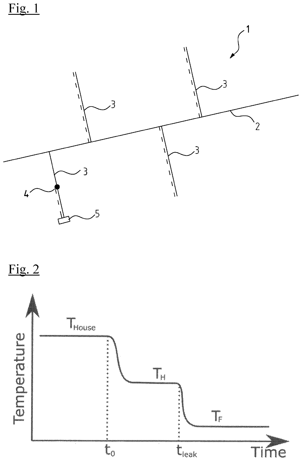
[0031]In FIG. 1 the principle of different temperatures in a water supply network 1 is shown in a very simplified schematical drawing. There is a main line 2 of the grid 1 with flowing water inside of a low temperature for example 12° C. As there is a big volume flowing through the main line 2 this temperature is nearly constant.

[0032]From this main line 2 secondary lines 3 branch off. These secondary lines lead to consumers, for example houses. Especially if there is little or no consumption on the consumption side for example in the night, the water temperature in the secondary lines 3 adapts to the temperature of the environment in the ground. This temperature may be for example 14° C. This higher temperature in the secondary lines 3 is shown in dotted lines.

[0033]n FIG. 1 in the lower left secondary line 3 there is a leak 4. As water is flowing through this leak 4 even if there is no consumption in this secondary line 3 there will be a low temperature up to the leak 4 correspond...


PUM


Abstract

A method for locating a leak (19) in a water supply network with a water source (11) and one or more water consumption meters (21, 22) on the consumer side. The method includes calculating a length of the pipe (17) between the consumption meter (21) and the leak (19) location based on a temporal temperature curve and a quantity of water flowing through the at least one consumption meter (21).

Description

CROSS REFERENCE TO RELATED APPLICATIONS[0001]Th application claims the benefit of priority under 35 U.S.C. §119 of European Application 21 167 496.5, filed Apr. 8, 2021, the entire contents of which are incorporated herein by reference.TECHNICAL FIELD[0002]The invention relates to a method for locating a leak in a water supply network and to a consumption meter configured for the implementation of this method.TECHNICAL BACKGROUND[0003]The most common water loses in water grids are caused by leaks in the pipe networks. Detecting and locating leaks in water networks can be done by using multiple technics. One of these technics is based on acoustics. When water exits a pressurized pipe through a leak, noise is generated. This noise can be used to detect and to locate the leak. Several methods exist and common to these are that the leak noise is captured using an analogue detecting device, i.e. microphones, hydrophones, accelerometers, piezo electric devices and the like. The detecting ...

Claims


Application Information

Patent Timeline
Patent Type & Authority Applications(United States)
IPC IPC(8): G01M3/00E03B7/00
CPCG01M3/002E03B7/003F17D5/06G01M3/243E03B7/072E03B7/078Y02A20/00
Inventor DUPONT, SUNE HOVEROUST
Owner KAMSTRUP
Why Eureka
Try Eureka