Eureka AIR delivers breakthrough ideas for toughest innovation challenges, trusted by R&D personnel around the world.

Smart Security Camera System with Automatically Adjustable Activity Zone and Method

Pending Publication Date: 2022-10-27
ARLO TECH INC
View PDF0 Cites 0 Cited by
  • Summary
  • Abstract
  • Description
  • Claims
  • Application Information

AI Technical Summary

Benefits of technology

The present invention provides a method and system for automatically adjusting the position of an activity zone in a security camera system. This is done by defining the activity zone in the initial field of view and updating the field of view in response to events, such as movement or a user demand. The system includes an imaging device and a detector that triggers a monitoring device upon detection of motion or other triggering events within the activity zone. The system can also include an accelerometer to detect movement. The method includes comparing the image of the activity zone with the updated field of view and automatically moving the activity zone to the determined position in the updated field of view. This ensures that the feature of interest remains in the monitored activity zone even if its position changes. The system can also include a user-operated user device or input device to define the initial position of the activity zone. The technical effect of this invention is to improve the efficiency and accuracy of security camera systems by automatically adjusting the position of the activity zone and ensuring that the feature of interest remains in the monitored activity zone.

Problems solved by technology

While functional for their intended purpures, these prior smart security imaging device systems have certain limitations.
Specifically, imaging devices in these prior smart security camera systems are often battery operated and, therefore, need periodic charging.
This apparent shift or displacement of the activity zone away from the area of interest may result in one or both of 1) in “false alarms” in which image capture and related operations are triggered by motion outside of the area of interest and 2) “missed alarms” in which motion in the area of interest is not detected.

Method used


Image

  • Smart Security Camera System with Automatically Adjustable Activity Zone and Method
  • Smart Security Camera System with Automatically Adjustable Activity Zone and Method
  • Smart Security Camera System with Automatically Adjustable Activity Zone and Method

Examples


Embodiment Construction

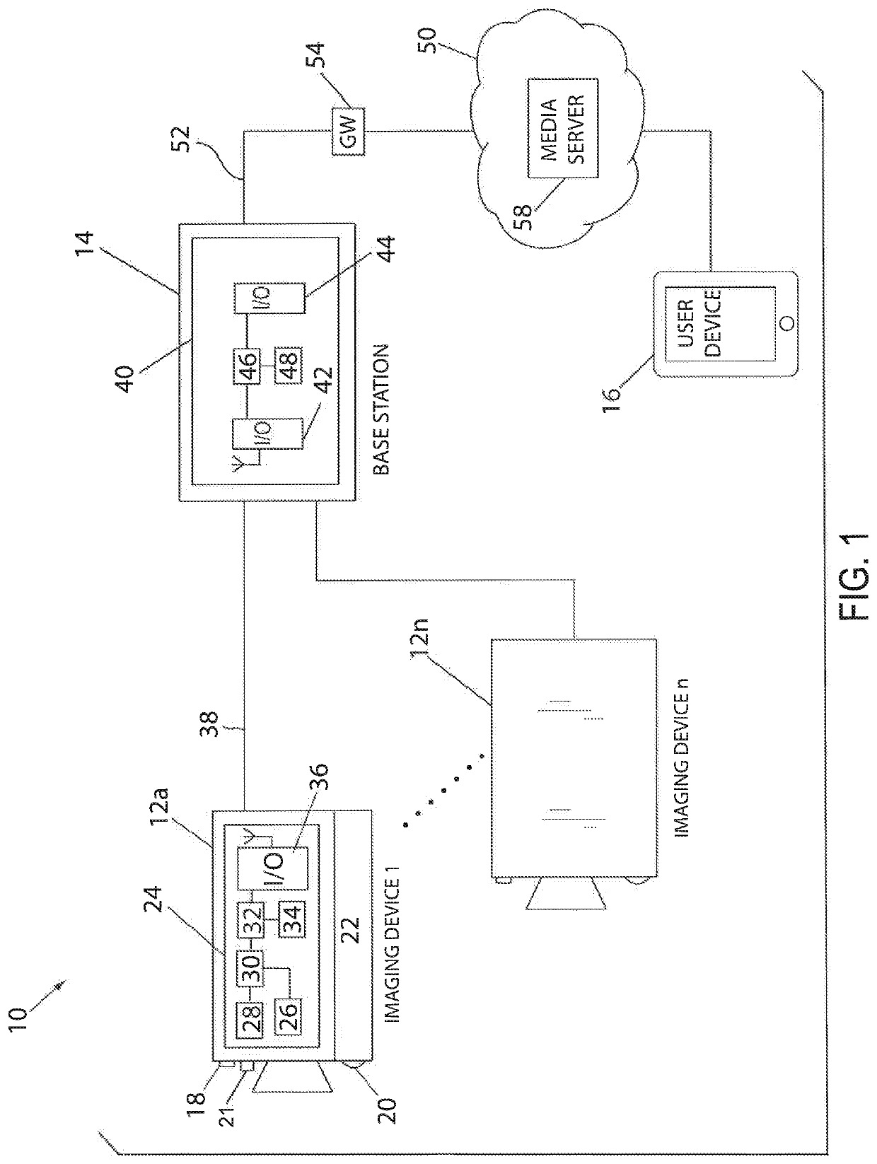
[0031]Referring now to FIG. 1, in accordance with an aspect of the invention, an electronic system or “smart security camera system”10 for real-time monitoring can include one or more imaging devices 12 and a hub or base station 14. A number “n”12a-12n of imaging devices are schematically illustrated in FIG. 1. One or more user devices or input devices 16, such as a smart phone, tablet, laptop, or PC communicate with the base station 14. Each user device includes a display that typically includes both an audio display and a video display, internal computing and storage capabilities, and a program or application servicing as a user interface with the remainder of the system 10.

[0032]Each imaging device 12 is configured to acquire data and to transmit it to the base station 14 for further processing and / or transmission to a server and / or the user device(s)16. Each imaging devices 12 may be battery powered or wired. The acquired data typically will correspond to a video image, and each...


PUM


Abstract

A method and a smart security camera system are provided for automatically adjusting an activity zone relative to a field of view of a security system imaging device such as video camera. The activity zone is within an initial field of view of the imaging device's camera and includes a monitored area of interest. An image of the activity zone is compared with an image of the updated field of view to determine a position of the activity zone relative to the area of interest in the updated field of view. The activity zone is automatically moved in the updated field of view to the determined position, if necessary. The activity zone thus is shifted a necessary within the updated field of view to encompass the area of interest.

Description

CROSS-REFERENCE TO A RELATED APPLICATION[0001]This application claims the benefit of provisional patent application U.S. App. No. 63 / 178,852, filed on Apr. 23, 2021 and entitled “SMART SECURITY CAMERA SYSTEM WITH AUTOMATICALLY ADJUSTABLE ACTIVITY ZONE AND METHOD”, the entire contents of which are hereby expressly incorporated by reference into the present application.BACKGROUND OF THE INVENTION1. Field of the Invention[0002]The present invention relates generally to electronic monitoring systems, and in particular, to a method and a smart security camera system for an electronic monitoring system that automatically adjusts the activity zone[s] in which motion is triggered if the field of view of an imaging device of the smart security camera system has shifted.2. Discussion of the Related Art[0003]Modern electronic monitoring systems for the home often include doorbells, along with video and audio communication technology. The typical electronic monitoring system includes a smart se...

Claims


Application Information

Patent Timeline
IPC IPC(8): H04N5/232H04N7/18
CPCH04N5/23229H04N7/188H04N7/18H04N7/181H04N23/80
Inventor MCRAE, MATTHEW
Owner ARLO TECH INC
Why Eureka
Eureka Blog
Learn More