Electrostatic discharge protection circuit

a protection circuit and electrostatic discharge technology, applied in the direction of semiconductor devices, electrical apparatus, transistors, etc., can solve the problems of circuit layout area waste, and achieve the effect of improving electrostatic discharge protection capability and saving circuit layout area

Pending Publication Date: 2022-11-03
WINBOND ELECTRONICS CORP
View PDF4 Cites 0 Cited by
  • Summary
  • Abstract
  • Description
  • Claims
  • Application Information

AI Technical Summary

Benefits of technology

[0007]Based on the above, the disclosure forms a diode between the bulk of the second transistor and a capacitor-resistor network for providing a bias voltage of the control terminal of the second transistor. Through the diode, when a negative voltage pulse is generated, a path may be provided to instantly conduct the first transistor, and the dissipating path

Problems solved by technology

Such approach often requires additional circuit e

Method used


Image

  • Electrostatic discharge protection circuit
  • Electrostatic discharge protection circuit
  • Electrostatic discharge protection circuit

Examples


Embodiment Construction

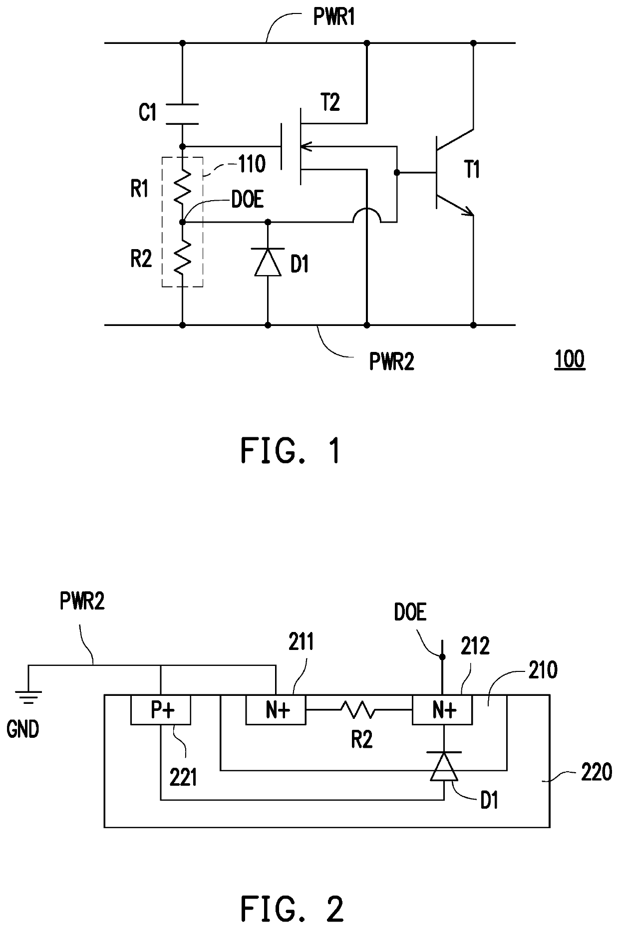
[0012]Please refer to FIG. 1. FIG. 1 is a schematic view of an electrostatic discharge protection circuit according to an embodiment of the disclosure. An electrostatic discharge protection circuit 100 includes transistors T1 and T2, a capacitor C1, a voltage dividing circuit 110, and a diode D1. The transistor T1 is coupled between a first power rail PWR1 and a second power rail PWR2. The transistor T2 is coupled between the first power rail PWR1 and the second power rail PWR2. A bulk of the transistor T2 is coupled to a control terminal of the transistor T1. In the embodiment, the transistor T1 is a bipolar junction transistor (BJT), and the transistor T2 may be a metal-oxide-semiconductor field-effect transistor (MOSFET). In detail, the transistor T1 may be an NPN-type BJT, and the transistor T2 may be an N-type MOSFET.

[0013]In the embodiment, the first power rail PWR1 may be used to receive a supply voltage, and the second power rail PWR2 may be used to receive a ground voltage....


PUM


Abstract

An electrostatic discharge (ESD) protection circuit includes a first transistor, a second transistor, a capacitor, a voltage dividing circuit, and a first diode. The first transistor is coupled between a first power rail and a second power rail. The second transistor is coupled between the first power rail and the second power rail. A bulk of the second transistor is coupled to a control terminal of the first transistor. The capacitor is coupled between the first power rail and a control terminal of the second transistor. The voltage dividing circuit is coupled between the control terminal of the second transistor and the second power rail, and has a divided voltage output terminal coupled to the bulk of the second transistor. The first diode is coupled between the divided voltage output terminal and the second power rail.

Description

CROSS-REFERENCE TO RELATED APPLICATION[0001]This application claims the priority benefit of Taiwan application serial no. 110115546, filed on Apr. 29, 2021. The entirety of the above-mentioned patent application is hereby incorporated by reference herein and made a part of this specification.BACKGROUNDTechnical Field[0002]The disclosure relates to an electrostatic discharge protection circuit, and in particular to an electrostatic discharge protection circuit that can improve the electrostatic discharge protection capability.Description of Related Art[0003]In the prior art, in order to ensure that an integrated circuit is not damaged by electrostatic discharge, an electrostatic discharge protection circuit is usually added to the integrated circuit to provide a dissipating path for an electrostatic discharge current and prevent circuit elements from being damaged. In the conventional technology, a power clamp circuit is often disposed between power rails as the electrostatic dischar...

Claims


Application Information

Patent Timeline
IPC IPC(8): H02H9/04H01L27/02
CPCH02H9/046H01L27/0285H01L27/027
Inventor SYU, JHIH-CHUNWANG, CHAO-LUNG
Owner WINBOND ELECTRONICS CORP
Why Eureka
Try Eureka