Fluid line for connection with a coupling

a technology of coupling and pipe, which is applied in the direction of hose connection, coupling, battery, etc., can solve the problem of not holding true for the outer diameter

Pending Publication Date: 2022-11-17
TI AUTOMOTIVE FULDABRUECK
View PDF0 Cites 6 Cited by
  • Summary
  • Abstract
  • Description
  • Claims
  • Application Information

AI Technical Summary

Problems solved by technology

While a precise inner diameter is comparatively easy to set by dr

Method used


Image

  • Fluid line for connection with a coupling
  • Fluid line for connection with a coupling
  • Fluid line for connection with a coupling

Examples


Embodiment Construction

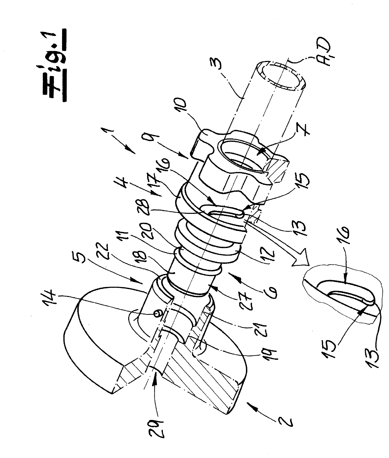
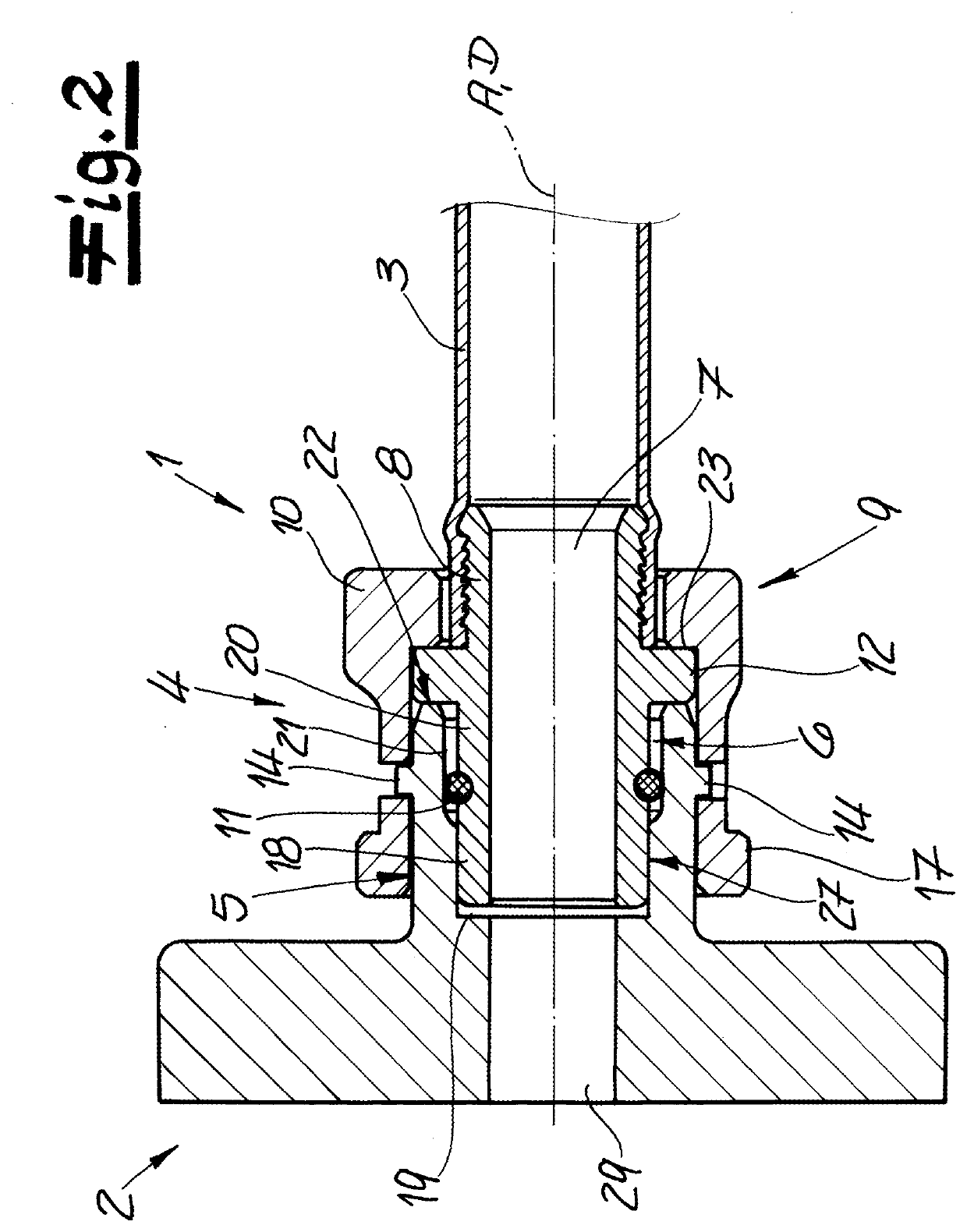
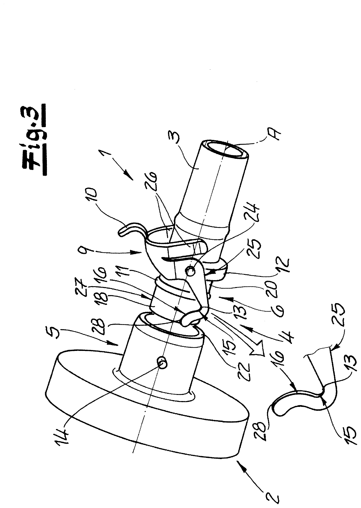
[0044]Shown on FIG. 1 is a first exemplary embodiment of a connector 4 according to the disclosure. The connector 4 comprises a main body 6 as well as a locking element 9, which in this exemplary embodiment is bayonetlike in design. The main body 6 and locking element 9 are preferably separately designed elements. The main body 6 and / or locking element 9 is / are (each) preferably one-piece or integral in design. The connector 4 is a component part of a fluid line 1, which apart from the connector 4 in particular has a tube 3 as well. The tube 3 is connected with the connector 4, as will be illustrated in somewhat more detail later. The connector 4 or main body 6 has a preferably cylindrically designed fluid channel 7. The fluid channel 7 or main body 6 defines an axis A, which preferably is a rotational axis or a longitudinal axis of the main body 6. It is expedient that the fluid channel 7 connect a first end of the connector 4 or main body 6 facing the coupling 5 with a second end ...


PUM


Abstract

A method for producing a tube arrangement for the transport of tempering medium, in which base body sections are provided, which have congruently configured separating surfaces, wherein at least one functional element on at least one base body section is arranged in such a way that it can be in contact with the tempering medium, whereafter the base body sections are joined along the separating surface and bonded to one another to form the tube arrangement.

Description

RELATED APPLICATIONS[0001]The present disclosure claims priority to and is a national phase application of European Application 21173854.7, filed on May 14, 2021, the entire contents of each of which are incorporated herein by reference.FIELD[0002]The present disclosure relates to a fluid line for connection with an assembly of a motor vehicle, comprising a tube or pipe and at least one connector, wherein the connector is designed for insertion into a complementary coupling, wherein the connector comprises a main body and a locking element for locking with the coupling, wherein the locking element is mounted relative to the main body so that it can rotate around a rotational axis D, wherein the connector or locking element is designed in such a way as to achieve a locking of the connector by rotating the locking element around the rotational axis D, wherein the locking element has a locking contour. The disclosure also relates to a fluid connection comprising this fluid line and a c...

Claims


Application Information

Patent Timeline
IPC IPC(8): F16L37/127H01M10/613H01M10/625H01M10/6567
CPCF16L37/127H01M10/613H01M10/625H01M10/6567H01M2220/20F16L37/248F16L2201/60F16L2201/10F16L37/113F16L37/20F16L33/20F16L1/065
Inventor JENSEN, HANSFIEDLER, UWE
Owner TI AUTOMOTIVE FULDABRUECK
Why Eureka
Try Eureka