Band-pass filter apparatus using superconducting integrated nonradiative dielectric waveguide

a filter apparatus and superconducting technology, applied in waveguides, superconductors/hyperconductors, resonators, etc., can solve the problems of single mode transmission, single mode transmission cannot be performed, single mode transmission band, etc., to achieve easy manufacturing, small size, and simple construction

Inactive Publication Date: 2000-01-04
MURATA MFG CO LTD
View PDF6 Cites 11 Cited by
  • Summary
  • Abstract
  • Description
  • Claims
  • Application Information

AI Technical Summary

Benefits of technology

An advantage of the present invention is that it is able to provide an NRD waveguide band-pass filter apparatus which solves the above-described problems, which is simple in construction and can be manufactured easily as well as being small in size and light in weight, and which operates in a single operating mode.
To achieve the above-described advantage, according to a first aspect of the present invention, there is provided an integrated NRD waveguide superconducting band-pass filter apparatus having a plurality of NRD waveguide resonators arrayed in such a way that each two adjacent NRD waveguide resonators are electromagnetically coupled to each other. The apparatus comprises: a hollow dielectric housing which is rectangular in cross-section and comprises an upper surface portion and a lower surface portion which are parallel to each other, and a plurality of arrayed dielectric waveguides, which are rectangular in cross-section and enclosed by the upper and lower surface portions; the upper and lower surface portions and the plurality of dielectric sections being formed integrally; first and second superconducting electrodes formed respectively on the outer surfaces of the upper surface portion and the lower

Problems solved by technology

In the arrangement of such filters, there is a problem in that it is difficult to adjust the external Q and the resonance frequency independently from each other.
The reason why single mode transmission cannot be performed in the conventional NRD waveguide is that a very small gap between the dielectric strip and the metal

Method used


Image

  • Band-pass filter apparatus using superconducting integrated nonradiative dielectric waveguide
  • Band-pass filter apparatus using superconducting integrated nonradiative dielectric waveguide
  • Band-pass filter apparatus using superconducting integrated nonradiative dielectric waveguide

Examples


first embodiment

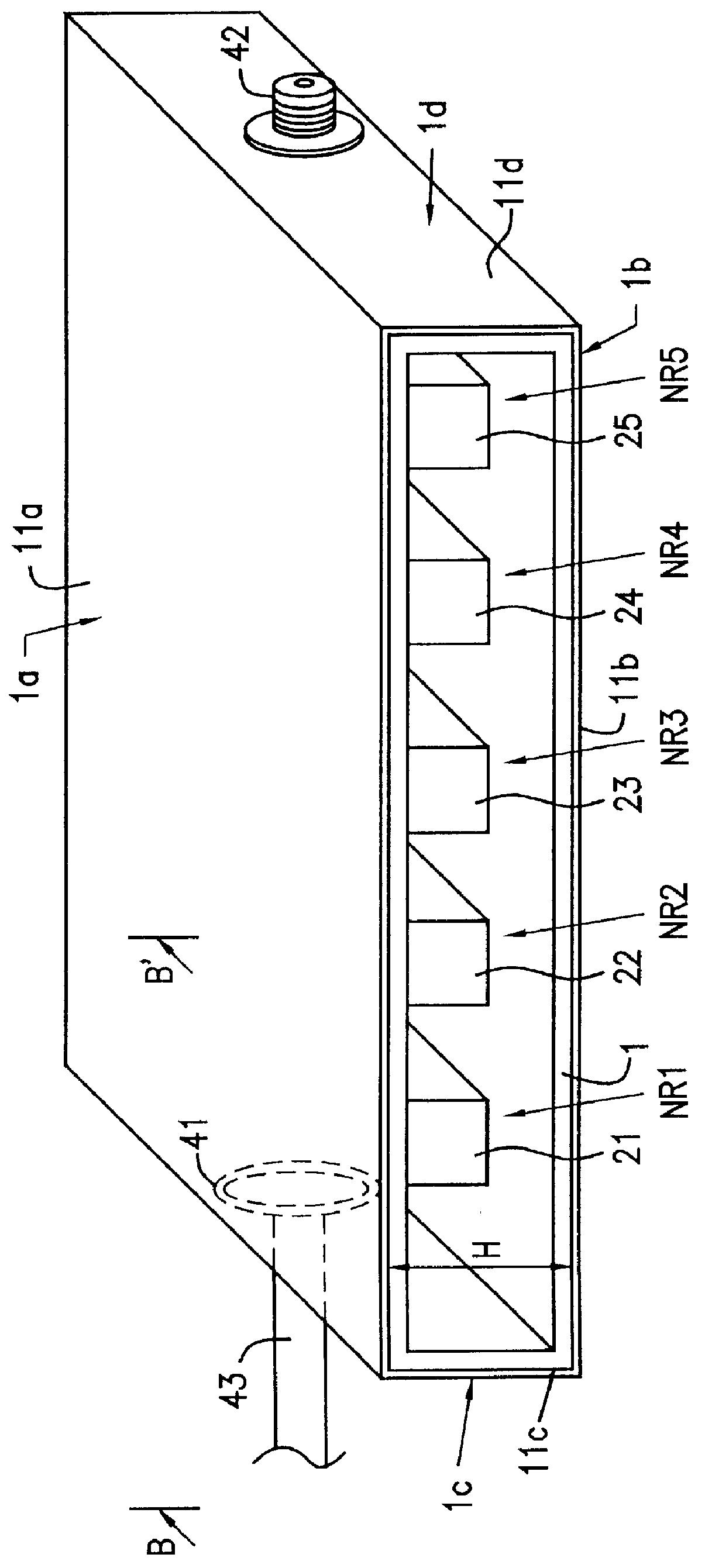
FIG. 1 is a perspective view illustrating the exterior of an integrated NRD waveguide superconducting band-pass filter apparatus according to a first embodiment of the present invention. A front view thereof is shown in FIG. 5, and a plan view thereof is shown in FIG. 6. In FIGS. 1, 5 and 6, a dielectric housing 1 made of dielectric materials, such as ceramics having a high dielectric constant, such as Ba(Sn,Mg,Ta)O.sub.3 or (Zr,Sn)TiO.sub.4, is formed integrally in such a way that dielectric waveguides 21, 22, 23, 24 and 25, each of which has a rectangular-prism shape, are interposingly disposed between an upper surface portion 1a and a lower surface portion 1b. The dielectric waveguides 21-25 have the shape of flat plates which face each other, with predetermined spaces S between them (the spaces S not being necessarily equal) each according to a predetermined coupling coefficient. The longitudinal end portions of the upper surface portion 1a and the lower surface portion 1b are r...

second embodiment

FIG. 2 is a perspective view illustrating the exterior of an integrated NRD waveguide superconducting band-pass filter apparatus according to a second embodiment of the present invention. The differences between the second embodiment and the first embodiment are that coaxial connectors 41 and 42 are provided as input / output terminals, and a coaxial waveguide 43 is used as a transmission waveguide. These different points will be described below.

As shown in FIGS. 2, 9A, and 9B, in the central portion of the end surface portion 1c on the side, a circular-shaped hole 41h is formed so as to open along the thickness direction of the end surface portion 1c and the electrode 11c. A coaxial connector 41 having a center conductor 41c is secured in the hole 41h by a ring 41f of the coaxial connector 41. A coaxial plug 43p is attached to the end portion of the coaxial waveguide 43 comprising a center conductor 43a and a grounding conductor 43b, and the coaxial plug 43p is inserted into the coax...

first modified embodiment

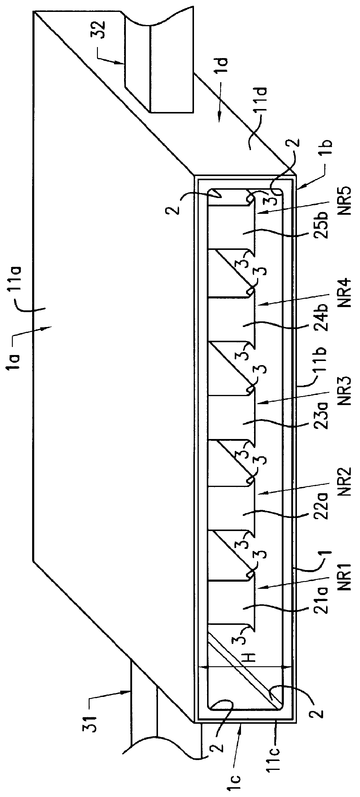
FIG. 3 is a perspective view illustrating the exterior of an integrated NRD waveguide superconducting band-pass filter apparatus according to a first modified embodiment of the present invention. In this first modification, as compared with the first embodiment, corners 2 at the connections between the upper surface portion 1a and the end surface portions 1c and 1d and between the lower surface portion 1b and the end surface portions 1c and 1d are chamfered so as to form a slope. Also, the bonding portions 3 between the dielectric waveguides 21a, 22a, 23a, 24b and 25b and the upper and lower surface portions 1a and 1b are chamfered to be rounded so that curved surfaces are formed from the side surfaces of the dielectric waveguides 21a, 22a, 23a, 24b and 25b to the upper surface portion 1a and the lower surface portion 1b. As a result, the effect of preventing cracks when stresses occur in dielectric materials, and the effect of increasing mechanical strength can be expected. Stresse...


PUM


Abstract

An NRD waveguide band-pass filter apparatus is provided which is simple in construction, which can be easily manufactured as well as being small in size and light in weight, and which operates in a single operating mode. The NRD waveguide band-pass filter apparatus includes a plurality of NRD waveguide resonators arrayed in such a way that each two adjacent NRD waveguide resonators are electromagnetically coupled to each other. A plurality of arrayed rectangular dielectric waveguides are interposed between an upper surface portion and a lower surface portion of a rectangular dielectric housing, which are parallel to each other. The upper surface portion and the lower surface portion and the plurality of arrayed rectangular dielectric waveguides are formed integrally, thus forming the housing. A first superconducting electrode and a second superconducting electrode are formed on the outer surfaces of the upper surface portion and the lower surface portion, respectively. By setting the spacing between the first and second superconducting electrodes at one-half or less of the wavelength of the resonance frequency in a vacuum of the present apparatus, the portions outside of each dielectric waveguide form cut-off regions.

Description

1. Field of the InventionThe present invention relates to an integrated superconducting band-pass filter apparatus employing nonradiative dielectric waveguides (hereinafter referred to as "NRD waveguides").2. Description of the Related ArtThe following arrangement is disclosed in Japanese Unexamined Patent Publication No. 3-270401. An NRD waveguide (hereinafter referred to as a "first conventional example") is formed with upper and lower portions of a dielectric waveguide shaped, for example, in a quadrangular prism, which are interposed and held by a pair of flat metal plates. The vertical height of the dielectric member taken at right angles to the direction of its length is a half-wavelength or less, a brim is extended from one side to the other at the upper and lower end portions in order to form an H-shaped cross-section, and a metallic film is formed in close contact with the outer surfaces of both upper and lower ends of the dielectric member including the brim portion, thus ...

Claims


Application Information

Patent Timeline
IPC IPC(8): H01P1/20H01P3/16H01P5/02H01P5/08H01P7/10
CPCH01P1/2002Y10S505/70Y10S505/866H01P7/10H01P1/207
Inventor ISHIKAWA, YOHEIHIDAKA, SEIJIMATSUI, NORIFUMI
Owner MURATA MFG CO LTD
Why Eureka
Try Eureka