Multi-Directional fasteners or attachment devices for spinal implant elements

a technology of spinal implant elements and fasteners, which is applied in the field of multi-directional fasteners or attachment devices for spinal implant elements, can solve the problems of nerve root injury, essentially impossible intraoperatively, fracture of pedicles of vertebrae, etc., and achieves the effects of increasing bone volume, enhancing locking engagement of links, and increasing vertebrae bone volum

Inactive Publication Date: 2000-02-01
ROGOZINSKI CHAIM
View PDF8 Cites 466 Cited by
  • Summary
  • Abstract
  • Description
  • Claims
  • Application Information

AI Technical Summary

Benefits of technology

This offset provides increased vertebrae bone volume as compared with prior art apparatus which overlie the vertebra surface, which increased bone volume can be used for bone grafts and fusion. In addition, the present invention permits visualization of bony maturation using plain X-rays since the links do not overlie the graft area.
The links of the present invention can be used with and secured to pedicle screws, bolts, or pedicle or laminar hooks. A combination of hooks and screws or bolts can be used as well depending on the particular application of the invention. For example, a laminar hook can be used on a lamina that is being fused to avoid damaging its associated facet (joint) such as would be caused by a screw or bolt.
The surface of the link member of the present invention is preferably provided adjace...

Problems solved by technology

In using such known plate systems, a problem arises when the points on the vertebrae defined by the screws or bolts are not collinear, i.e., they do not lie in a straight line.
This creates a problem for the physician because the openings in the plate are collinear and, therefore, the screws do not line up with the plate openings.
Due to the thickness and high strength of the plate, this is essentially impossible to do intraoperatively.
This creates an immediate high stress region in the screw or bolt which can cause failure of the same upon cyclical loading or, even worse, can lead to a fracture of the pedicle of the vertebra....

Method used


Image

  • Multi-Directional fasteners or attachment devices for spinal implant elements
  • Multi-Directional fasteners or attachment devices for spinal implant elements
  • Multi-Directional fasteners or attachment devices for spinal implant elements

Examples


Embodiment Construction

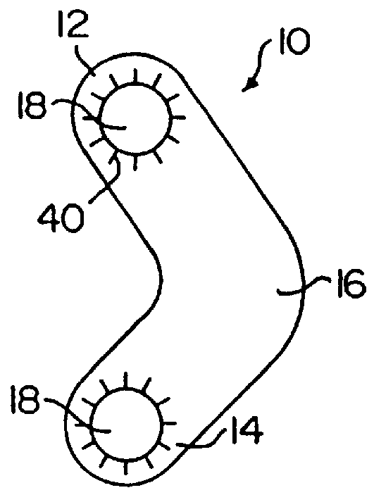
With reference to FIG. 1A, a link member according to a first embodiment of the present invention is indicated generally by the reference numeral 10 and includes first and second end portions 12, 14 and a central portion 16. The end portions 12, 14 each have an aperture 18 therein which apertures are configured to receive a threaded bone bolt or screw, or a laminar or pedicle hook, to secure the link 10 to adjacent vertebrae as will be described below. The link 10 is preferably integrally formed so as to comprise a one-piece structure. The link in the embodiment of FIG. 1A is in the form of a plate and is substantially V-shaped with the central portion 16 comprising the apex of the V shape.

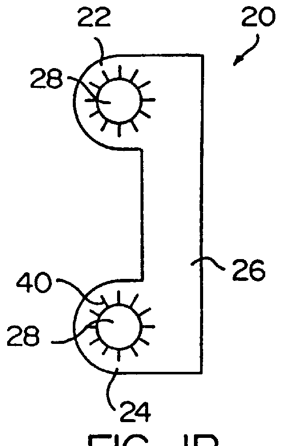
FIG. 1B shows another embodiment of the link according to the present invention indicated generally at 20. Link 20 includes first and second end portions 22, 24 and a straight central portion 26. The end portions 22, 24 each have an aperture 28 similar to the apertures 18 in link 10. Link 20 also ...


PUM


Abstract

An apparatus, method and system for treating spinal conditions by moving or spatially fixing at least one vertebra relative to another vertebra. The invention includes a link member the ends of which are configured to be secured to adjacent vertebrae and which are offset from a central portion of the link member. The link members can be in the form of a C-shaped or V-shaped rod or plate to form the offset. The offset provides increased bone volume that can be used for grafts or fusion. Attachment structure in the form of bone screws, bolts, or hook members are provided to secure the link members to respective vertebrae or other bones. A plurality of link members can be connected in chain-like fashion to connect multiple points on a plurality of vertebrae or other bones even though those points are nonlinear. In another aspect of the invention, a multi-directional attachment member is provided and may be used with the link members to form a spinal implant or external bone fixation system.

Description

BACKGROUND OF THE INVENTION1. Field of the InventionThe present invention relates generally to apparatus and methods for treating and correcting spinal abnormalities or conditions, stabilizing the position of the spine and vertebrae thereof and fixing or moving the position of bones other than those in the spine. More specifically, the present invention provides an apparatus and system which includes a plurality of links usable together under various circumstances to treat, e.g., different spinal curvature conditions or bone fractures.2. Description of the Relevant ArtThe prior art includes many different apparatus and methods for treating spinal conditions. Known apparatus utilize elongate plate members having several aligned openings or an elongated slot therein for receiving screws or bolts that are affixed to vertebrae. The plate is secured to the screws or bolts and exerts force on the selected vertebra or vertebrae to move same into a desired position or to maintain same in a ...

Claims


Application Information

Patent Timeline
IPC IPC(8): A61B17/56
CPCA61B17/56A61B17/7037A61B17/7032A61B17/7038A61B17/7041A61B17/7007A61B17/7011A61B17/701
Inventor ROGOZINSKI, CHAIM
Owner ROGOZINSKI CHAIM
Why Eureka
Try Eureka