Inspection method and apparatus for the inspection of either random or repeating patterns

Inactive Publication Date: 2000-02-01
KLA INSTR
View PDF4 Cites 90 Cited by
  • Summary
  • Abstract
  • Description
  • Claims
  • Application Information

AI Technical Summary

Benefits of technology

3. The hybrid technique can do additional frequency-domain processing virtually for free--for example, the shading problem can be solved (low frequency fluctuations across the image are eliminated by a high pass filter with a very low cut-off frequency), undesirable effects of the MTFs (modulation tr

Problems solved by technology

Further, the relative offsets of the pairs of images are determined by frequency d

Method used


Image

  • Inspection method and apparatus for the inspection of either random or repeating patterns
  • Inspection method and apparatus for the inspection of either random or repeating patterns
  • Inspection method and apparatus for the inspection of either random or repeating patterns

Examples


Example

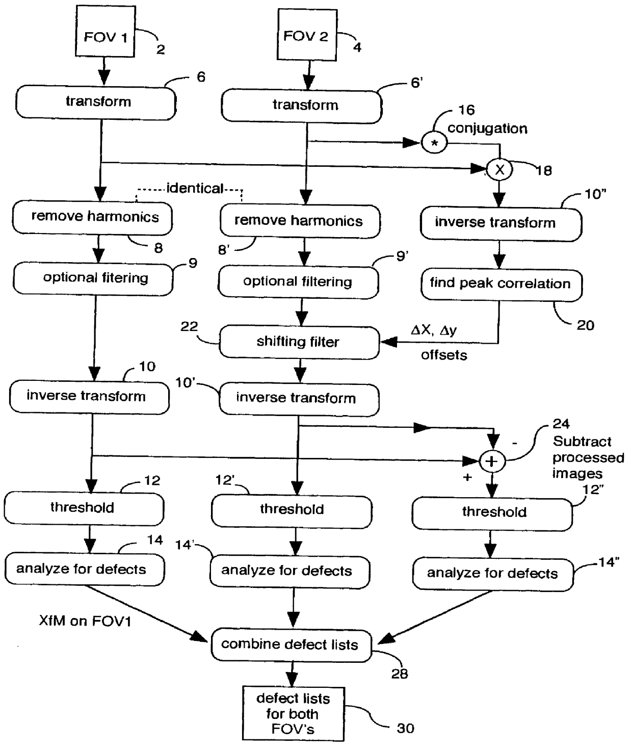
The present invention, in order to inspect both random and repeating patterns which may or may not be present on the same device, includes electronic techniques which are capable of high speed inspection of both types of patterns.

One may think of the image of a device pattern as being a superposition of four images: a random image; a repeating image; a noise image; and a defects image. That can be represented mathematically as

where

i(x,y)=total device image;

rn(x,y)=random image portion of the device;

rp(x,y)=repeating image portion of the device;

n(x,y)=noise image (due to sensor, lighting or reflective fluctuations, etc.); and

d(x,y)=defect image or defect map (image changes due to defects).

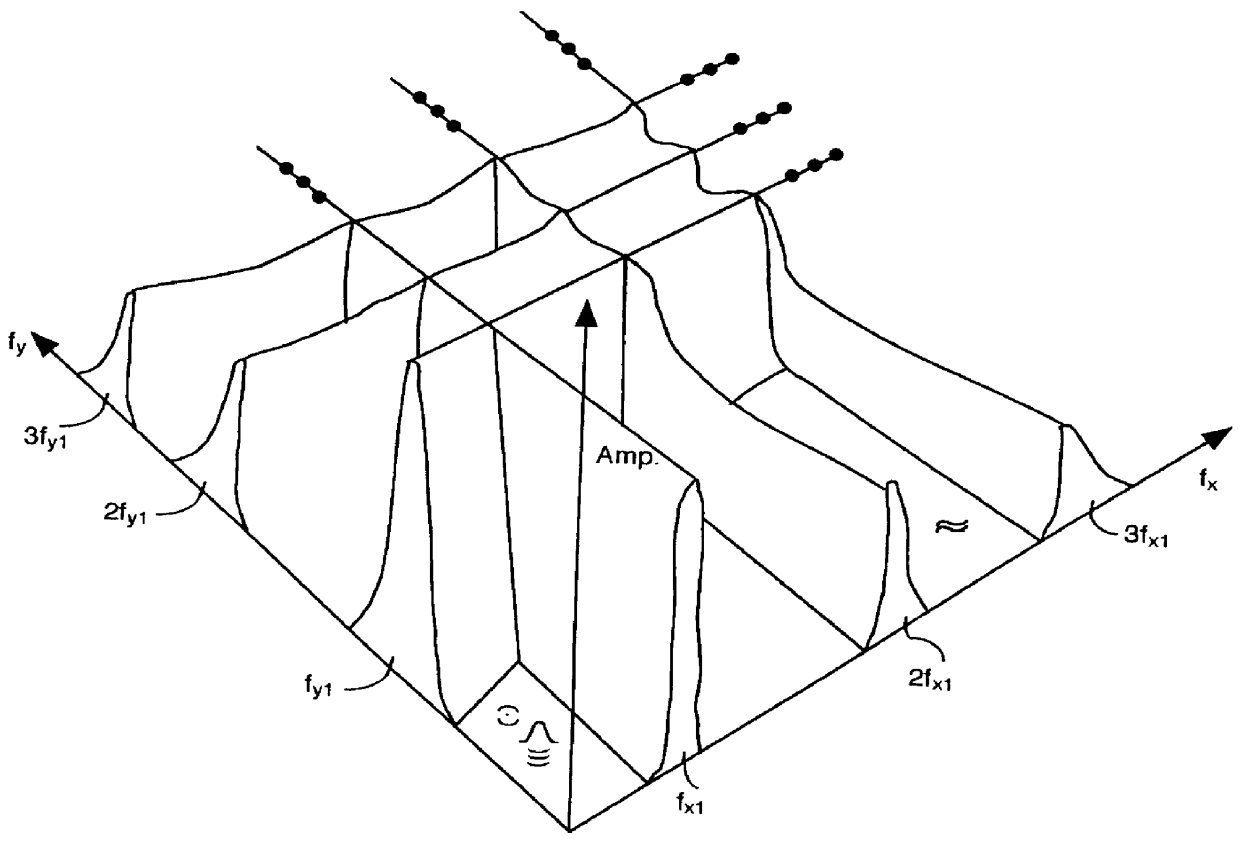
Let the spectrum of the device image be

where

RN(f.sub.X,f.sub.Y)=the spectrum of rn(x,y)

RP(f.sub.X,f.sub.Y)=the spectrum of rp(x,y)

N(f.sub.X,f.sub.Y)=the spectrum of n(x,y)

D(f.sub.X,f.sub.Y)=the spectrum of d(x,y)

f.sub.X =the frequency in the x direction

f.sub.Y =the frequency in the y direction

The sp...


PUM


Abstract

The present invention is a hybrid technique for finding defects on digitized device images using a combination of spatial domain and frequency domain techniques. The two dimensional spectra of two images are found using Fourier like transforms. Any strong harmonics in the spectra are removed, using the same spectral filter on both spectra. The images are then aligned, transformed back to the spatial domain, and subtracted. The resulting spectrally-filtered difference image is thresholded and analyzed for defects. Use of the hybrid technique of the present invention to process digitized images results in the highest-performance and most flexible defect detection system. It is the best performer on both array and random devices, and it can cope with problems such as shading variations and the dark-bright problem that no other technique can address. The hybrid technique of the present invention also uses frequency domain techniques to align the images with fewer errors than spatial domain techniques of similar or lesser complexity. Further, the relative offsets of the pairs of images are determined by frequency domain techniques--and this method may be the most accurate and the least expensive.

Description

FIELD OF THE INVENTIONThe present invention is related to the inspection of a first device pattern by comparing that device pattern with a second device pattern where those patterns may be on different dies, different device patterns on the same die, repeating patterns within the same device, on paper, or stored in memory. More particularly, the present invention relates to device pattern inspection where the pattern to be inspected is a random pattern, a repeating pattern, or a combination of the two.BACKGROUND OF THE INVENTIONThe types of patterns that are found on devices, particularly those in the production of semiconductor devices, are categorized as either random, repeating, or a combination of the two. This categorization is important in that, historically, random and repeating patterns have been inspected optically in the spatial domain, whereas repeating patterns are more easily inspected in the frequency domain. Also, in the early semiconductor technologies the repeating ...

Claims


Application Information

Patent Timeline
IPC IPC(8): G06T5/10G06T7/00G06K9/52G06K9/64
CPCG03F7/7065G06K9/00G06K9/522G06T7/0004G06T7/0036G06K9/6202G06T2207/30148G06T2207/20056G06T7/37G06V10/431G06V10/751G06F18/00
Inventor EVANS, DAVID M. W.TSAI, BIN-MING BENLIN, JASON Z.
Owner KLA INSTR
Why Eureka
Try Eureka