Head and disk tester with a thermal drift-compensated closed-loop positioning system

a positioning system and head and disk technology, applied in the direction of maintaining head carrier alignment, process and machine control, instruments, etc., can solve the problem of not being able to change the temperature rate the same, and achieve the effect of eliminating the temperature drift of the magnetic head position and accurate positioning of the magnetic head

Inactive Publication Date: 2000-02-08
GUZIK TECHN ENTERPRISES
View PDF5 Cites 39 Cited by
  • Summary
  • Abstract
  • Description
  • Claims
  • Application Information

AI Technical Summary

Benefits of technology

It is an object of the present invention to provide a head / disk tester that effects accurate positioning of a magnetic head with respect to magnetic disk in a tester, even in the case of unstable temperature conditions. Another object of the invention is to provide a method of positioning that eliminates the temperature drift of the magnetic head position in such head / disk testers. One more object is to provide a head / disk tester that ensures positioning repeatability, for example, on the order of 0.0025 .mu.m (0.1 .mu.in) during any test, regardless of how long it takes.

Problems solved by technology

Moreover, the rate of temperature change is not the same for different parts due to differences in their heat transmission and storage characteristics.

Method used


Image

  • Head and disk tester with a thermal drift-compensated closed-loop positioning system
  • Head and disk tester with a thermal drift-compensated closed-loop positioning system
  • Head and disk tester with a thermal drift-compensated closed-loop positioning system

Examples


Embodiment Construction

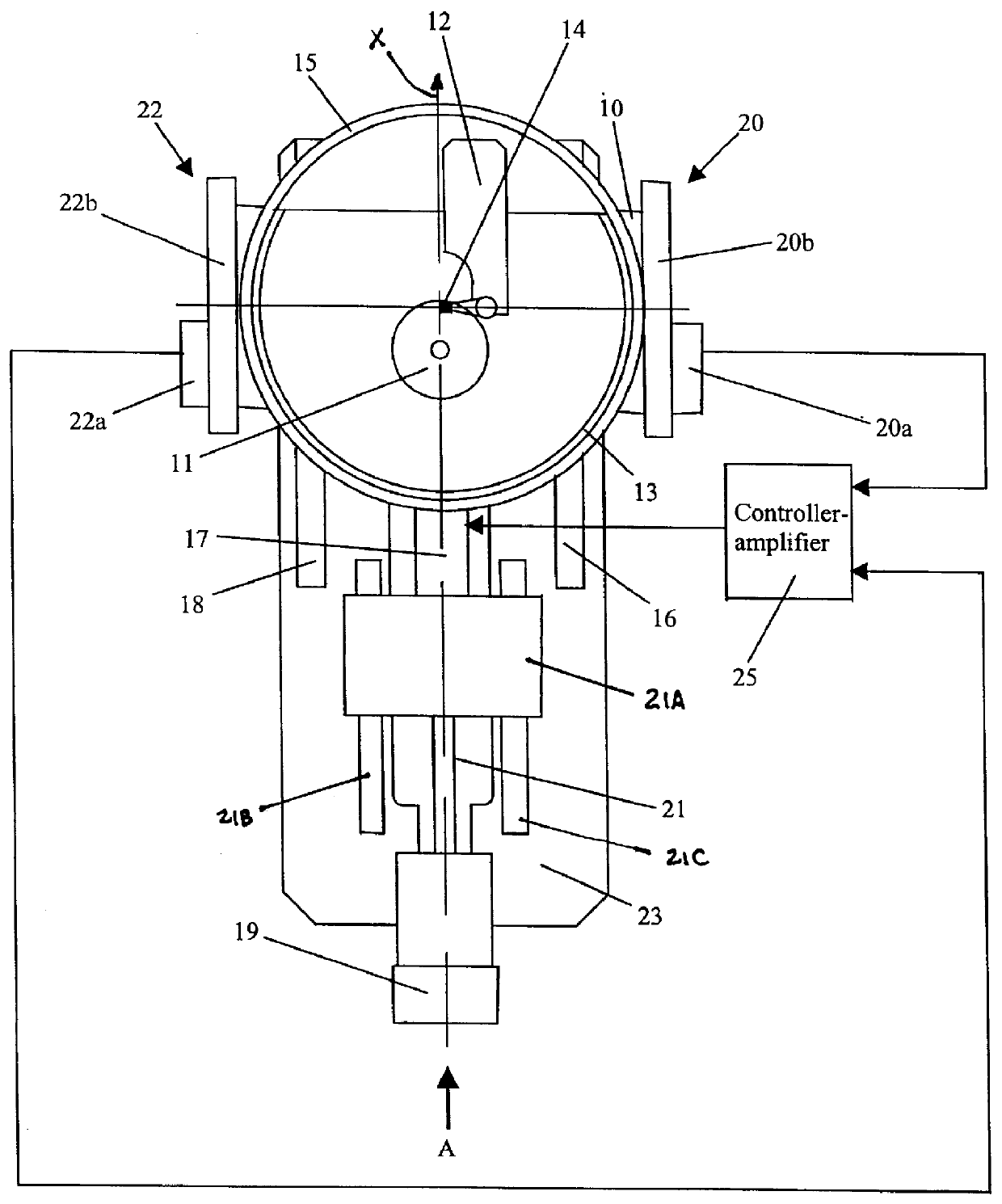
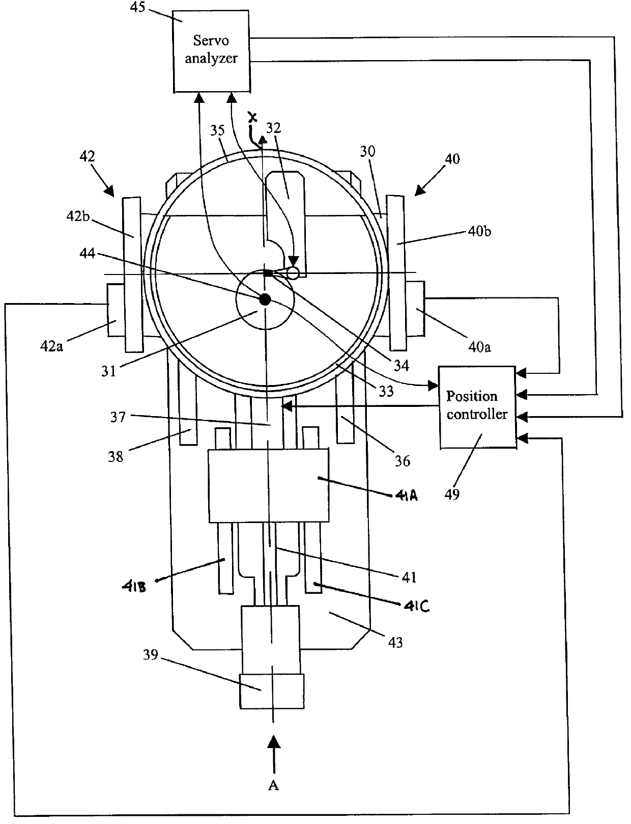
An exemplary head / disk tester of the invention, with a thermal drift-compensated closed-loop positioning system, is schematically shown in FIG. 2. Similar in many respects to the prior art head / disk tester of FIG. 1, the head / disk tester of FIG. 2 has a base 43 that supports a carriage 30 guided along horizontal (X-axis) rails 36 and 38 in the direction of arrow A. Carriage 30 supports an outer ring 35 that in turn supports an inner ring 33, centered about the intersection of the X and Y axes of a horizontal coordinate system on carriage 30. The inner ring 33 carries a magnetic head support 32 with a magnetic head 34 to be tested. The carriage 30 is driven linearly in the direction indicated by arrow A by a stepper motor 39 through a lead screw 41 coupled to an intermediate block 41A (slidable in the X direction on horizontal rails 41B and 41C). Carriage 30 in turn is driven with respect to block 21A in the X-direction by a piezo actuator 37. Another stepper motor (not shown) is use...


PUM

PropertyMeasurementUnit
temperatureaaaaaaaaaa
widthaaaaaaaaaa
magneticaaaaaaaaaa

Abstract

The head/disk tester of the invention has a housing 43 that houses spindle 44 that rotatingly supports a magnetic disk 31. The housing supports a moveable carriage 30 that, in turn, supports a magnetic head 32. Positioning means 39 and 41 are used to move the carriage and the magnetic head across the magnetic disk. These positioning means include stepper motors that realize coarse positioning of the magnetic head, and a piezo actuator 37 that is used for fine positioning. Linear encoders 40 and 42 located at both sides of the carriage provide feedback information to a closed-loop positioning system that controls the piezo actuator. A set of special signals ("servo bursts") pre-written at a given track of the magnetic disk is used as an additional source of feedback information for the same closed-loop positioning system. This positioning system includes a servo analyzer 45 that reads and processes servo burst signals from the magnetic disk, and a position controller 49 that controls the piezo actuator. The controller contains two control loops: a proportional-integral-derivative (PID) loop and an additional servo burst loop. During any movement of the magnetic head to a prescribed command position, the servo burst feedback is turned off, and feedback from linear encoders is used by the PID loop to move the head. When the magnetic head reaches the prescribed command position, servo burst loop is turned on; it changes the command position of the PID loop in a way to keep the ratio of pre-written burst signals constant. As a result, the position of the magnetic head with respect to the data track remains the same for as long as necessary, even in unstable temperature conditions.

Description

The present invention relates to magnetic head / disk testers, in particular, to testers of the aforementioned type with a closed-loop positioning system and to a method for eliminating thermal drift of magnetic head position in such testers.High-capacity computer storage devices typically include one or more electromagnetic transducers and a corresponding number of magnetic media disks. The transducers, also known in the art as "heads", are adapted for transfer of electronic information between a data source, for example a computer, and data locations on the magnetic disks. Information is communicated in accordance with well-known conventions and formats that enable high-density storage, rapid access to data locations, high reliability, data integrity, and device miniaturization, writing and reading of data is accomplished with a read / write head positioned over a disk.In general, information is stored on and read from disks in "tracks", which are regions of width T which extend along...

Claims


Application Information

Patent Timeline
Patent Type & Authority Patents(United States)
IPC IPC(8): G11B5/55G11B5/455G11B21/08G11B5/596G11B21/10
CPCG11B5/455G11B5/5552G11B5/5565G11B5/596
Inventor KARAASLAN, UFUKBOKCHTEIN, ILIASTEIN, ANATOLIGUZIK, NAHUMVARLAKHANOV, ALEXANDER
Owner GUZIK TECHN ENTERPRISES
Why Eureka
Try Eureka