Method of controlling magnetic tape unit

a magnetic tape unit and control method technology, applied in the direction of moving record carriers backward/forward, digital recording, instruments, etc., can solve the problems of recording massive amounts of data on the magnetic tape, the inability to expand the compressed data read in a backward direction in response to a read back command, and the general inability to expand the compressed data through the edrc system. , to achieve the effect of enhancing the performance of ror processing, reducing processing time, and increasing hardwar

Inactive Publication Date: 2000-02-15
FUJITSU LTD
View PDF13 Cites 26 Cited by
  • Summary
  • Abstract
  • Description
  • Claims
  • Application Information

AI Technical Summary

Benefits of technology

Further, at the same time when the plurality of data blocks read in the forward direction are written in the data buffer, the read commands concerning the data blocks read in the forward direction are stored in the command queue in reverse order to how the data blocks are read. It is thereby possible to continuously transfer the data blocks in the data buffer to the host processor even when the read back commands are continuously issued as in the case of...

Problems solved by technology

Therefore, an EDRC compression mechanism is used to compress data, and the compressed data is recorded on the magnetic tape, thereby recording massive amounts of data on the magnetic tape.
However, it is impossible to expand the compressed data read in a backward direction in response to a read back command.
As stated above, it is generally impossible to expand the data compressed through the EDRC system with the data arranged in the backward direction.
Consequently, the ROR processing must be performed for each data block, resulting in a considerably long processing time.
Hence, the MTU 30 must separately perform the piecemeal mechanical operation for each data block, thereby requiring a significant long process...

Method used


Image

  • Method of controlling magnetic tape unit
  • Method of controlling magnetic tape unit
  • Method of controlling magnetic tape unit

Examples


Embodiment Construction

A description will now be given of an embodiment of the present invention referring to the accompanying drawings.

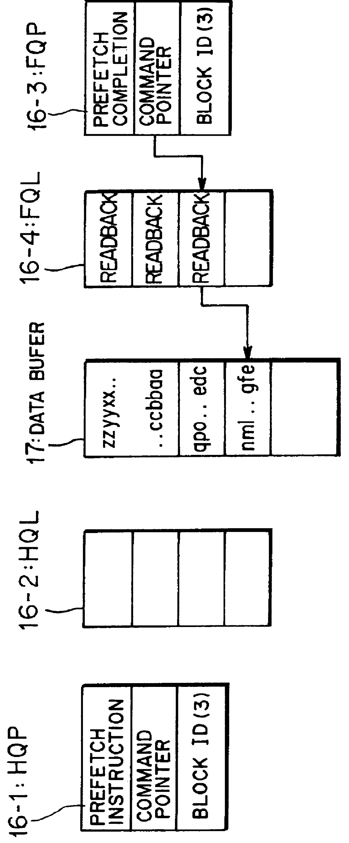
A magnetic tape controller to which a method of controlling a magnetic tape unit of the present invention is applied has the same hardware configuration as that of the magnetic tape controller (see reference numeral 10) discussed above with reference to FIGS. 27 and 28, and a description thereof is omitted. In the following discussion, the same reference numerals are used for component parts identical or equivalent to those illustrated in FIGS. 27 and 28.

In the embodiment, neither a CPU (host computer, host processor) 20 nor an MTU (magnetic tape unit) 30 is varied in both hardware and software. However, only a change in firmware is made to an MTC (magnetic tape controller) 10.

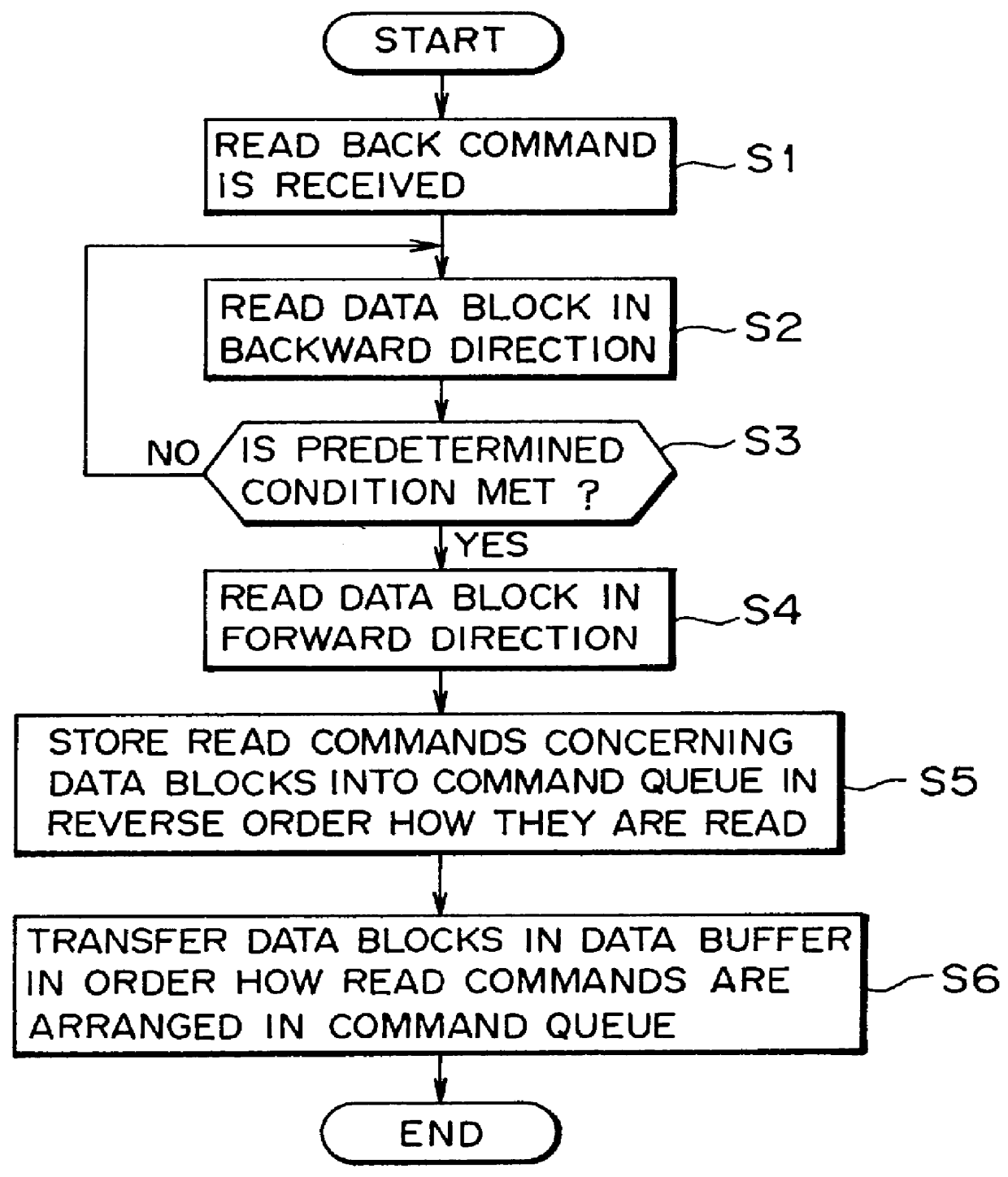
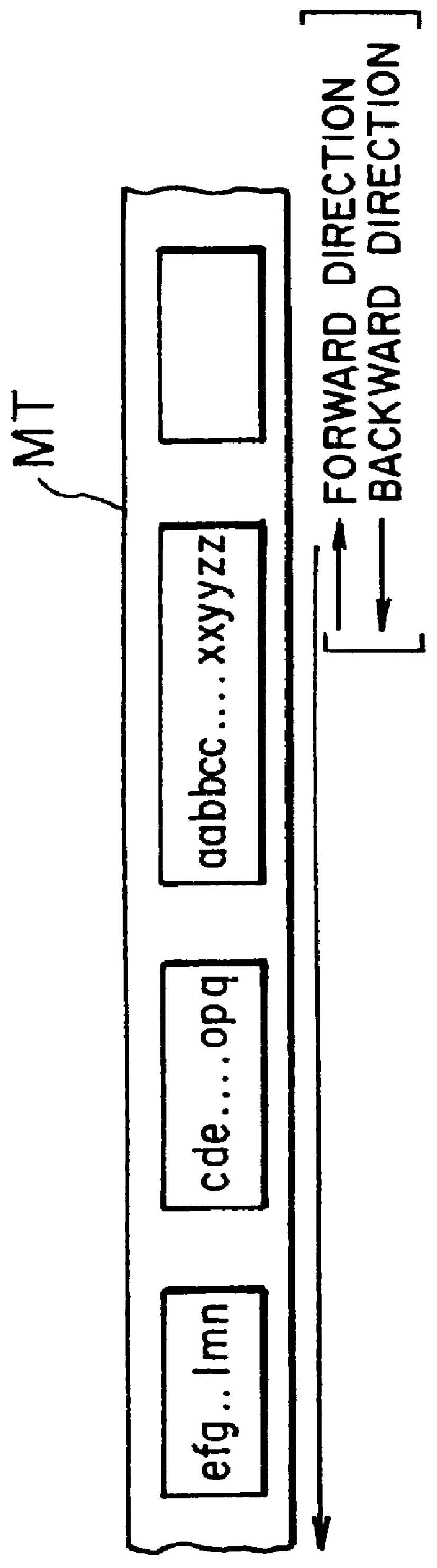
A description will now be given of the method of controlling the magnetic tape unit according to the embodiment of the present invention referring to FIGS. 1 to 26.

Writing is continuously performed ...


PUM


Abstract

The present invention is made such that data in a buffer can be transferred even when read back commands are continuously issued so as to completely eliminate the need for a mechanical operation required for each data block in ROR processing, resulting in considerably reducing a processing time. For this purpose, a method of controlling a magnetic tape unit of the present invention includes the steps of, when the read back command is received from a host processor, reading plurality of data blocks, when a read position of an MTU meets a predetermined condition, reading in a forward direction a plurality of data blocks in the range between the position and a start position of the read back command so as to write the data blocks into the data buffer, storing read commands concerning the data blocks into a command queue in reverse order to how the data blocks are read, and thereafter, in response to a read command from the host processor, reading the data blocks in the data buffer in the order in which the read commands are arranged in the command queue so as to transfer the data blocks to the host processor after data expansion. Further, the invention is applied to a magnetic tape unit to write data compressed through, for example, an EDRC system onto a magnetic tape, and read the compressed data therefrom.

Description

1) Field of the InventionThe present invention relates to a technique applied to a magnetic tape unit to write on a magnetic tape (storage medium) data compressed through, for example, an EDRC (Enhanced Data Recording Capability) system, and read the compressed data. More particularly, the invention relates to a method of controlling a magnetic tape unit, for performing ROR (Read Opposite Retry) processing required after read back of the compressed data.2) Description of the Related ArtIn recent years, more efficient backup / restore operations in which data is copied between a DASD (Direct Access Storage Device) and a magnetic tape have been desired for a requirement for a higher speed computer system. Therefore, an EDRC compression mechanism is used to compress data, and the compressed data is recorded on the magnetic tape, thereby recording massive amounts of data on the magnetic tape.In general, when the data compressed through the EDRC system is read from the magnetic tape, it is...

Claims


Application Information

Patent Timeline
IPC IPC(8): G11B15/20G11B15/18G11B15/02G11B27/10G11B27/30G06F3/06G11B15/087G11B27/36G11B5/09G11B20/10
CPCG06F3/0613G06F3/0656G06F3/0682G11B15/02G11B15/1875G11B15/20G11B27/107G11B27/3027G11B15/087G11B27/36G11B2220/90
Inventor MASE, TOMONORIENOHARA, KATSUOSHIMURA, OSAMU
Owner FUJITSU LTD
Why Eureka
Try Eureka