Method of fabricating a permanent magnet line start motor having magnets outside the starting cage

a technology of permanent magnets and starting cages, which is applied in the direction of magnetic bodies, magnetic circuit rotating parts, magnetic circuit shapes/forms/construction, etc., can solve the problems of poor performance of induction motors, insufficient induction torques, and inability to start some motors

Inactive Publication Date: 2000-02-29
REGAL BELOIT ELECTRIC MOTORS INC
View PDF25 Cites 45 Cited by
  • Summary
  • Abstract
  • Description
  • Claims
  • Application Information

AI Technical Summary

Problems solved by technology

Resulting induction torques, however, are not always high enough to start some motors because the induction cage is magnetically interrupted and often electrically interrupted as well.
The result is poor performance as an induction motor.
Moreover, the rotor cage can never be fully magnetically uniform and complete because that would "short circuit" the magnetic flux of the magnets allowing little or no magnetic flux to reach the air gap for interaction with the stator currents.
The result is that the cage does not produce torque as effectively as it would if complete.
Thus, fabricating a flux barrier permanent magnet motor with inside magnets results in an ineffective induction motor.

Method used


Image

  • Method of fabricating a permanent magnet line start motor having magnets outside the starting cage
  • Method of fabricating a permanent magnet line start motor having magnets outside the starting cage
  • Method of fabricating a permanent magnet line start motor having magnets outside the starting cage

Examples


Embodiment Construction

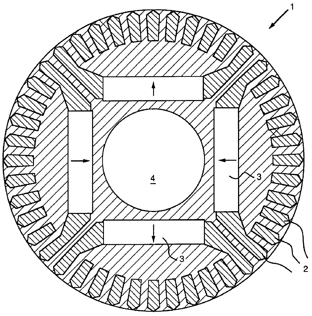
FIG. 1 is a sectional side view of a rotor 1 having a shaft 4 for a conventional line start permanent magnet motor wherein a plurality of magnets 3 are positioned inside an induction starting rotor cage 2.

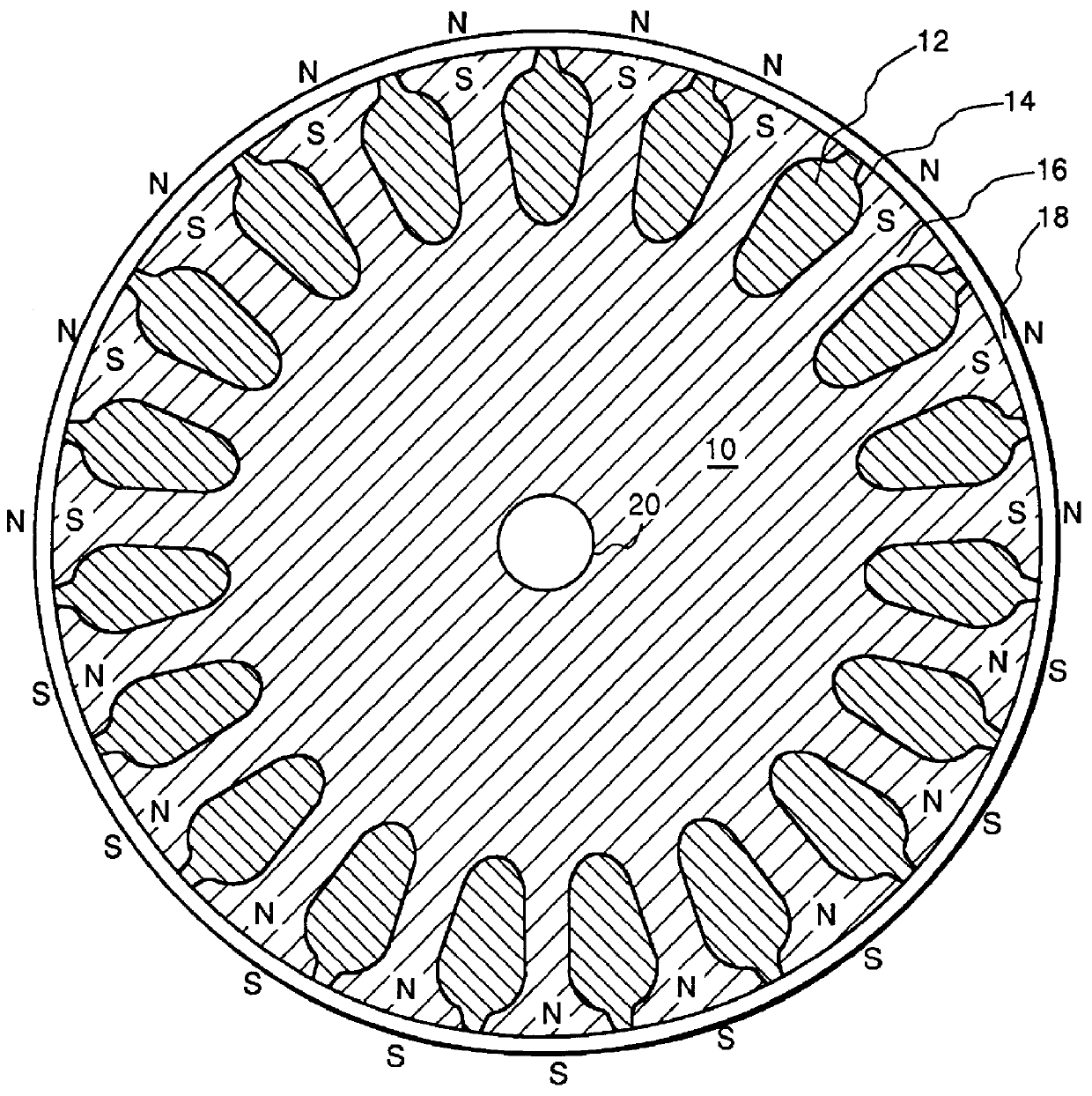
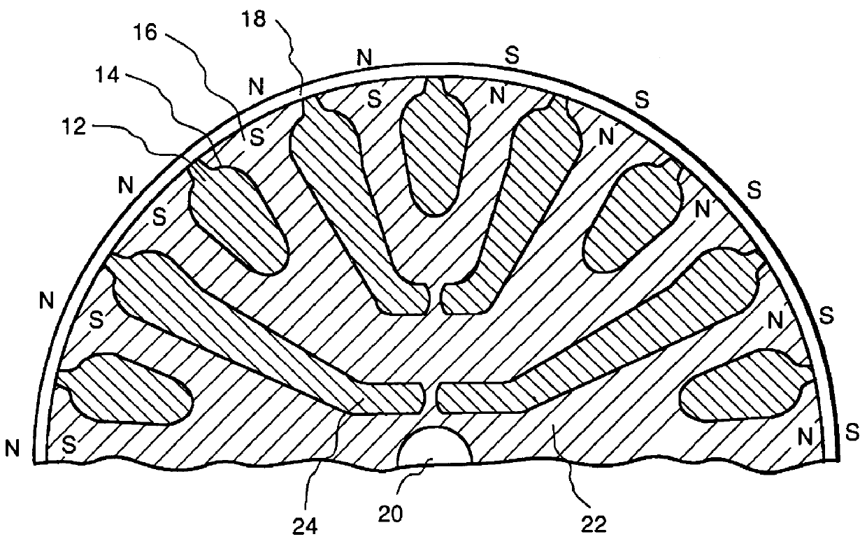
FIG. 2 is a sectional side view of an embodiment of a rotor core 10 of the present invention having a shaft 20 and teeth 16 defining slots 14 for placement of a rotor cage 12 (a short-circuited rotor winding). In this embodiment rotor 10 is a conventional induction motor rotor which is coated with a thin magnetized layer of high energy composite permanent magnet material 18. The manufacturing process is therefore much simpler than that of conventional PM synchronous motors. In one embodiment the thickness of the layer of permanent magnet material is about 1 / 64 of an inch, for example which could yield as much as 4000 gauss in the air gap of a small motor. The rotor typically comprises several hundred laminations of metal sheets such as iron or steel with slots 14 punched therethrou...


PUM

PropertyMeasurementUnit
thickaaaaaaaaaa
thickaaaaaaaaaa
perimeteraaaaaaaaaa

Abstract

A rotor for use in a line start permanent magnet motor comprises a rotor core having a shaft and including teeth defining slots; a rotor cage, at least a portion of which extends through the slots; and a layer of composite permanent magnet material at least partially coating the rotor core.

Description

1. Field of the InventionThis invention relates generally to line start permanent magnet motors and, more specifically to line start motors having magnets outside starting cages and magnetization of such motors.2. Description of the Related ArtConventional line start permanent magnet motors are designed with the magnets inside the induction starting cage. In these motors, large block magnets can be used. The magnets inside the cage are only partially protected from demagnetization during starting (when the rotor flux can be 180 degrees out of phase with the stator flux at very high current levels). When the line voltage at full frequency is applied to a stopped motor winding, the air gap magnetic field revolves very rapidly past the stationary rotor magnets and thus (although strong pulsating torques exist) develops no net torque. The motor is instead started by currents flowing in the starting cage exactly as in an induction motor. Resulting induction torques, however, are not alwa...

Claims


Application Information

Patent Timeline
Patent Type & Authority Patents(United States)
IPC IPC(8): H02K21/46H02K15/03H02K1/27H02K21/00
CPCH02K1/2726H02K15/03H02K21/46Y10T29/49076Y10T29/49012
Inventor KLIMAN, GERALD BURTPRESTON, MARK ALANJONES, DONALD WAYNE
Owner REGAL BELOIT ELECTRIC MOTORS INC
Why Eureka
Try Eureka